Pre-installation checklist, 2 lifting the display, Lifting the display – Daktronics AF-3400-12-RGB User Manual
Page 10: Figure 4: lifting the display
Pre-installation Checklist
Verify the following before proceeding with installation:
•
The display is in good condition after shipping and uncrating.
• All clip angles or mounting holes are attached to the support structure.
• A straight and square mounting frame is provided for the display.
Height variation in any four-foot horizontal section may not exceed ¼-inch.
• Adequate support is provided for the display so that the structure will not yield at
any unsupported points after mounting.
• Clearance of 4" of unobstructed space above the top of the display is allowed to
remove the eyebolt. Note: No clearance is required once the eyebolt is removed.
• Clearance in front of the display is maintained to allow unobstructed air flow
through the vents and to allow access to internal components.
2.2 Lifting the Display
The top of the display is equipped with eyebolts that are used to lift the unit. Take special
care to ensure that the rated load of the eyebolts is not exceeded. Refer to the information at
the end of this section labeled Eyebolts to determine the allowable load of the eyebolts
shipped with the display.
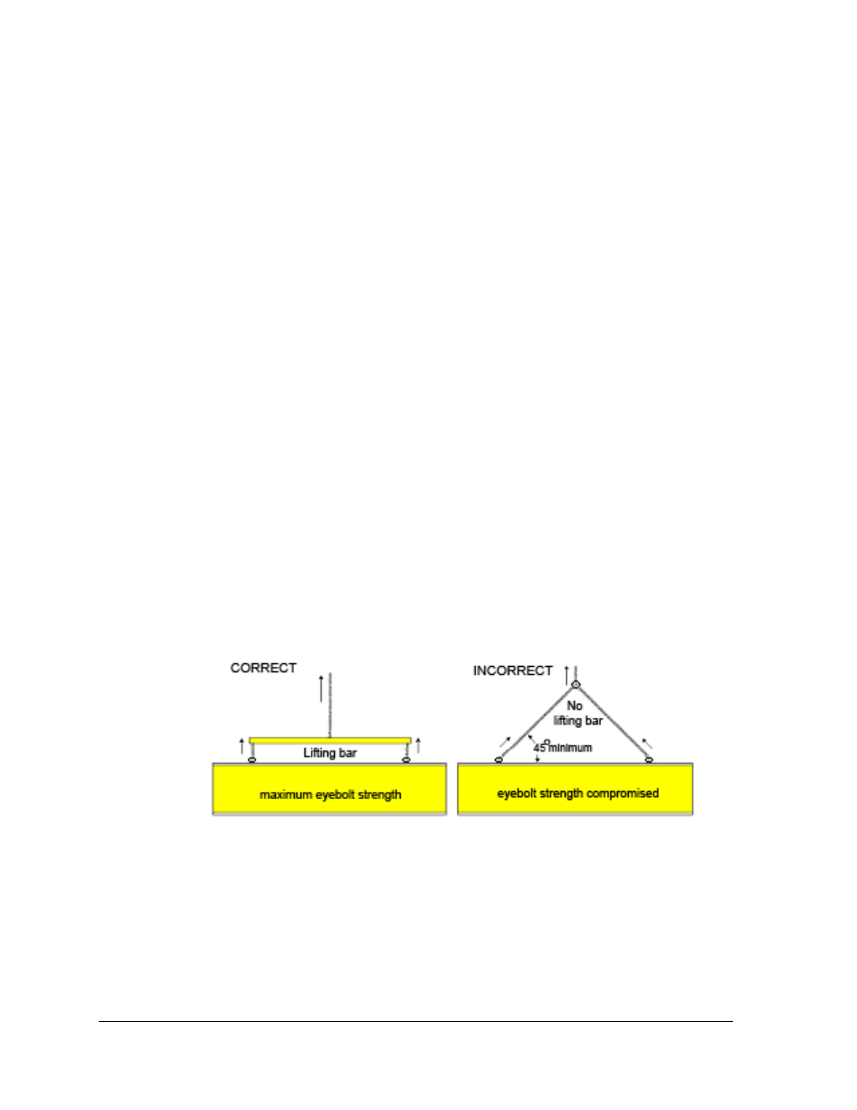
Figure 4 illustrates both the correct (left example) and the incorrect (right example) method
of lifting a display. Lift the display as shown on the left, with the lifting bar. Use every lifting
point provided.
Figure 4: Lifting the Display
Do not attempt to permanently support the display by the eyebolts.
Eyebolts can be removed after mounting to eliminate the need for overheard clearance.
Mechanical Installation
4