Figure 28: controller component layout, Controller – Daktronics AF-3400-12-RGB User Manual
Page 44
Controller
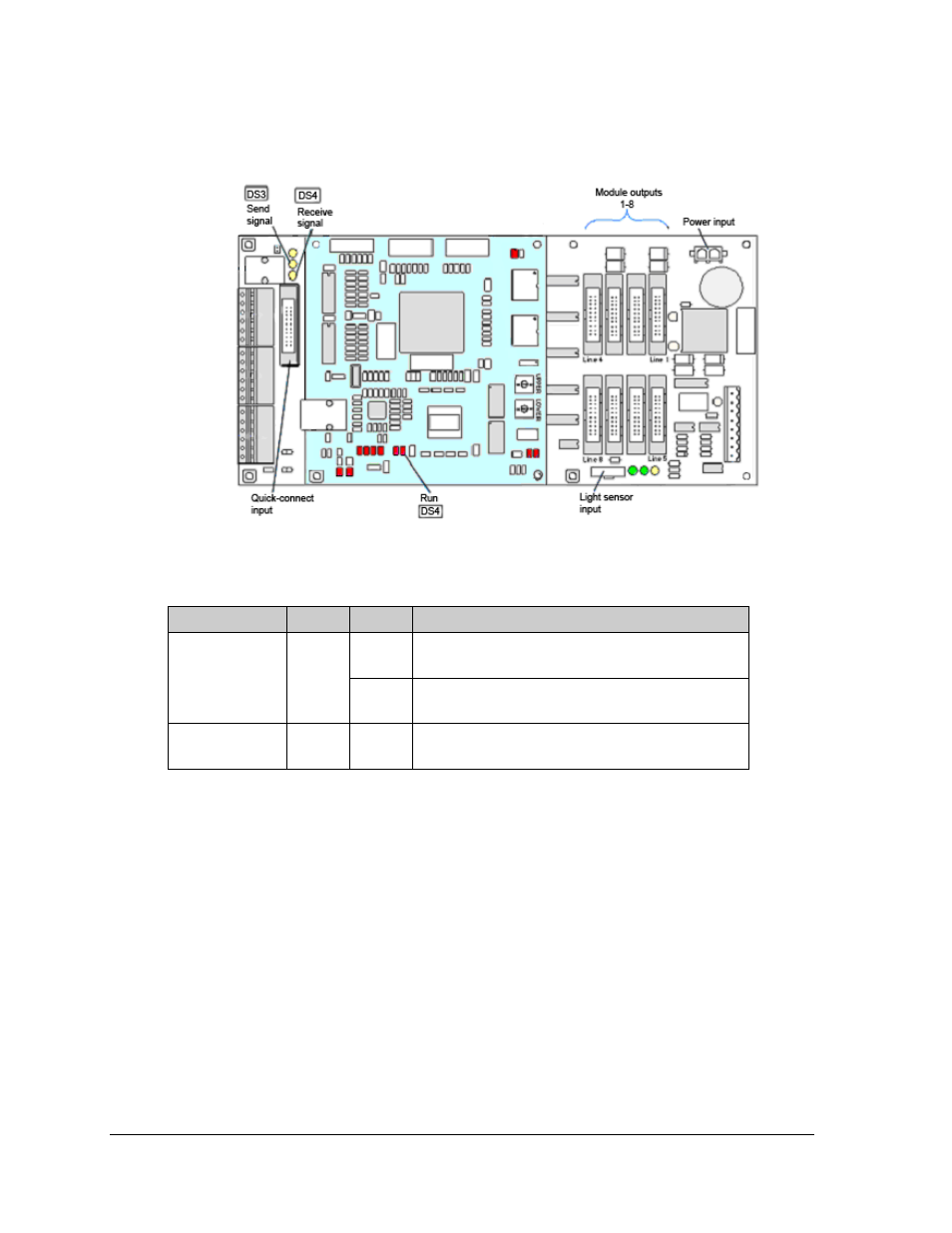
The controller's role is to send data to the modules. Figure 28 illustrates a typical controller.
Figure 28: Controller Component Layout
Diagnostic LEDs are located on the controller. The table below tells what each LED denotes:
Figure/ label
LED #
Color
Operation
Run
DS4
Red
Steady FLASH about once per second indicates
controller is working properly.
Send signal
TX1
DS3
Yellow
OFF is the normal state. FLASH when transmitting
communication from the computer.
Receive signal
RX1
DS4
Yellow
OFF is the normal state. FLASH when receiving
communication from the computer.
Complete the following steps to remove or replace the controller in the display:
1. Turn off power to the display.
2. Remove the module directly in front of the controller in the lower left corner of the
display.
3. Disconnect the power plug from J5.
4. Remove all power and signal connections from the board, labeling the cables as they
are disconnected.
5. Remove the six nuts holding the board in place using a 5/16" nut driver.
6. Take note of the address of the controller and ensure the address on the replacement
board is the same.
Follow the previous steps in reverse order to install a new controller board.
Maintenance and Troubleshooting 38