Ethernet bridge radio communication, Figure 18: ethernet bridge radio layout, 8 ethernet bridge radio communication – Daktronics AF-3400-12-RGB User Manual
Page 29
•
Refer to the software manual for other possible conditions.
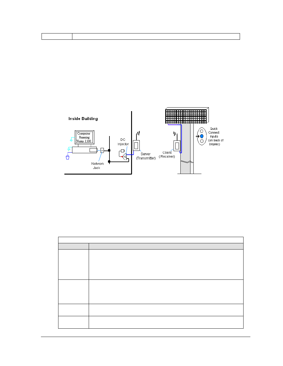
4.8 Ethernet Bridge Radio Communication
If the communication system is a wireless Ethernet radio, look for:
• a DC injector connected to the network, server radio, and DC power pack.
• a server (transmitter) radio mounted on the building and a client (receiver) radio at
the display.
Note: This system is referred to as Ethernet "bridge" communication because it requires a pair
of matched radios to create a signal connection or bridge.
Figure 18: Ethernet Bridge Radio Layout
Connections
• Computer to network − RJ45 cable from computer port into network jack.
• Network jack to DC injector - RJ45 cable from network to "DATA IN" jack.
• Wall power pack - DC injector power pack to 120 VAC outlet.
• DC injector to server radio - RJ45 cable from "P+DATA OUT" to server radio.
• Server radio to client radio - clear line of sight for signal transmission.
• Client radio to display − quick-connect cable to the middle jack on display back.
Troubleshooting
Component Check
Cable
Connections
• A cable connects the computer to the network port on the wall.
• A cable runs from the network to the DC injector.
• The DC injector power pack is plugged into a 120 VAC outlet.
• A network cable runs from DC injector to server radio.
• A cable is connected from the client radio to the top jack on back of display.
Diagnostic
LEDs
• The DC injector's green LED should be on, indicating power.
• Both radios have internal LEDs: red for power, green for RF link.
• The RX and TX LEDs will flash when transmitting data.
• The same channel LEDs will be on for both radios when locked together.
Display
Power
• The display is either running a message or showing a single pixel flashing in
the bottom right corner of the display when power is on.
Software
• The software is configured for TCP/IP communication.
• The software and the display are set for the same network address.
Signal Overview
23