Daktronics AF-3080-68-R,A User Manual
Page 49
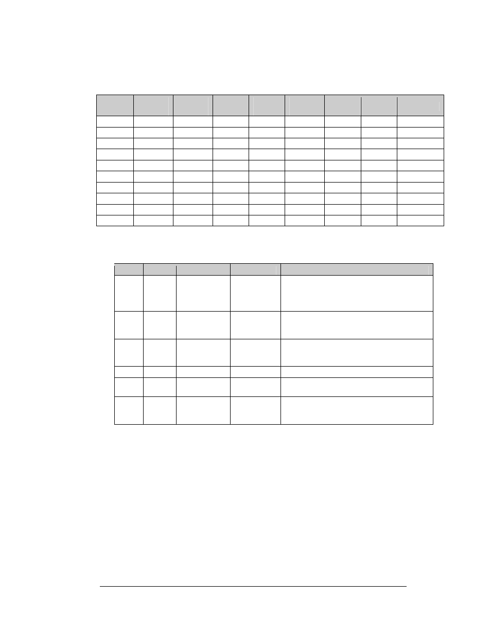
Note: Setting the DIP switches to address 0 (turn all the switches to off by
flipping them toward the printed switch numbers) can activate a test mode. The
display’s power must be turned off and then turned back on to run the test mode.
Switch
8
Switch
7
Switch
6
Switch
5
Switch
4
Switch
3
Switch
2
Switch
1
Address
Off Off Off Off Off Off Off Off
Test
Mode
Off Off Off Off Off Off Off On 1
Off Off Off Off Off Off On Off 2
Off Off Off Off Off Off On On 3
Off Off Off Off Off On Off Off 4
Off Off Off Off Off On Off On 5
Off Off Off Off Off On On Off 6
Off Off Off Off Off On On On 7
… … … … … … … … …
On On On On Off Off Off Off 240
Six diagnostic LEDs are located on the controller; the table below tells what each
LED denotes:
LED
Color
Function
Operation
Summary
TEMP Red
Temperature
Level
Flashes
Flash rate is dependent upon the
temperature. Flashes faster in high
temperature and slows as the temperature
decreases.
LGHT Red
Photocell
Light Level
Flashes
Flash rate is dependent on the light level.
Flashes faster in bright light and slows as
darkness descends.
RUN Red Controller
Steady
Flash
A steady flash indicates the controller is
running correctly. Normal flash rate is about
once a second.
PWR
Green
Power
Always On
Power to the data input circuit when lit.
RX1
Yellow
Com 1
Flashes
Turns on and flashes when receiving
information. Normal condition is off.
RX2
Yellow
Com 2
Flashes
Turns on and flashes when receiving
information, typically used in custom
applications. Normal condition is off.
To remove the controller from the display:
1. Disconnect power from J2.
2. Remove all power and signal connections from the board. “Locked”
connectors are released by squeezing together the tabs, and then carefully
pulling them from the jack. When replacing the board, it is helpful to have
the cables labeled as to which was removed from which connector.
3. Remove each of the six screws holding the board in place.
4. Follow the previous steps in reverse order to install a new controller board.
Maintenance and Troubleshooting
4-7