Component identification, Component identification -4, 4 component identification – Daktronics AF-3080-68-R,A User Manual
Page 12
Refer to the drawings referenced above for the approximate size, weight, and power
requirements for your model of sign.
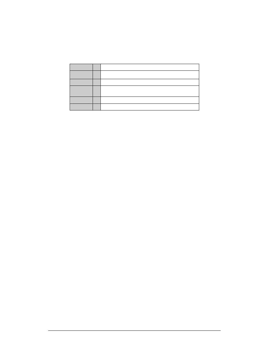
The following describes the Galaxy model numbers: AF-3080-RRxCCC-68-X-XF
AF-3080 =
Outdoor 68 mm Galaxy Sign
RR
=
Number of Rows High
CCC
=
Number of Columns Wide
68
=
68 mm center-to-center spacing with 18" minimum
character height
X
=
LED Color (monochrome red or amber)
XF
=
SF or DF (Single face or Double face)
A typical sign system consists of a Windows
â
based personal computer (PC) running
Venus
â
1500 software and one or more signs. Daktronics offers the signs as single-
face units, which are single-sided stand-alone signs. They can become double-faced
by mounting them back-to-back with a second unit.
The Venus
®
1500 is a software package that runs under Windows
®
98, ME
™
, NT
®
4.0, 2000, or XP Home/Professional operating systems on an IBM
®
-compatible
computer. Refer to the Venus
®
1500 operator's manual, ED-13530, for installation
and operation of the Venus
®
1500 editing stations.
Refer to Section 4 for the summaries of how signal and power are routed through the
displays.
1.4 Component
Identification
The following illustrations and definitions depict some of the more commonly
accessed Galaxy sign components. Because Daktronics occasionally alters standard
design to meet customer needs, the actual sign design may vary slightly from the
illustrations below.
This is only a brief overview. Refer to Section 4 for detailed information on
maintaining and troubleshooting various sign components.
Com Port: Connector on the back of the control computer. The COM port controls
the sign through either a 9- or a 25-pin serial connector.
Introduction
1-4