Modules and drivers, Modules and drivers -7, Figure 37: removing a module – Daktronics AF-3112-34-R,A User Manual
Page 43
Product
Board
LED Color
Function Operation
DS1
Green
+5V
On when +5V power supply is functioning.
DS2
Green
+3.3V
On when +3.3V power supply is functioning.
DS3
Yellow
COM1 TxD
Flashes when transmitting serial information.
DS4
Yellow
COM1 RxD
Flashes when receiving serial information.
Temp/Light
Sensor
LED Color
Function Operation
DS1
Green
+5V
On when +5V power supply is functioning.
DS2
Red
Run
A steady flash indicates the controller is running correctly.
Normal flash rate is about once a second. Flashes faster
when the sensor is transmitting temp or light information.
Modules and Drivers
Reference Drawings:
Schem, AF-3112-8-32X*****-34mm-Mono-PM ............ Drawing C-200002
The module and driver board are a single functional unit. The LED power supplies
are identified as assemblies.
•
In displays with 2 red LEDs per pixel, each power supply unit controls up to
five modules.
•
In displays with 3 amber LEDs per pixel, each power supply unit controls
up to five modules.
To remove a module, complete the following steps:
1. Locate the latch access fasteners on the front of the display. With a 5/32”
hex wrench turn the
latch fasteners a
quarter turn as shown
in Section 3.5 for
opening the display
front.
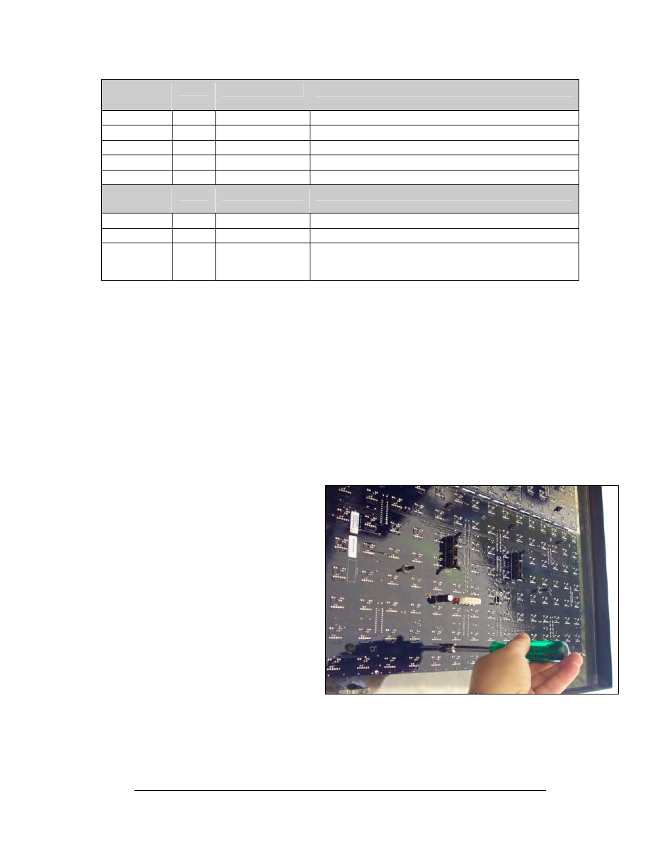
Figure 37: Removing a Module
2. Disconnect and label
the wires cables to the
module.
3. Remove the ten, 5/16”
nuts holding the
module to the face
panel and the louvers.
Gently pull the module
away from the face
panel.
4. When installing a
module, reverse the
previous steps.
Maintenance and Troubleshooting
4-7