Signal termination from network to display, Rs232, Signal termination from network to display -9 – Daktronics AF-3112-34-R,A User Manual
Page 29: Rs232 -9, Figure 21: rs232 display layout, 7 signal termination from network to display
3.7 Signal Termination from Network to Display
Reference Drawing:
Schem, AF-3112-8-32X***-34mm-Mono-PM............... Drawing C-200002
The AF-3112 is designed for quicker connection to the computer and to the Mirror
display. Refer to Drawing C-200002 for electrical terminations.
• Signal will terminate to a watertight enclosure, which connects to the
primary display using a quick connect cable.
• The temp sensor will mount to the display and terminate to the primary
display with a quick connect cable.
•
The primary display will connect to the mirror display with a quick connect,
inter-connect cable.
RS232
Reference Drawings:
System Riser Diagram, RS232 Comm. Box ................ Drawing A-199104
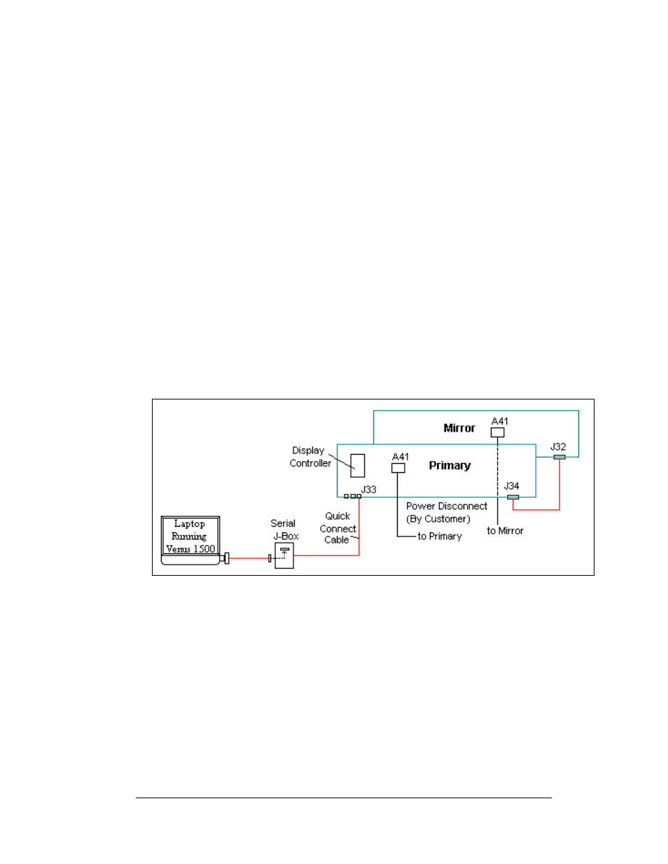
A RS232 controlled display connections are in a weather resistant enclosure to be
mounted within 25 feet of the display, as shown below in
. From the
enclosure to the display, the signal will be connected to the primary using a quick
connect cable. Do not run signal and display power through the same conduit.
Figure 21: RS232 Display Layout
Note: The cable from the enclosure to the display can be routed though conduit, or
should be secured to prevent being pulled loose from the display by weather or
vandalism.
1. Mount the enclosure within 25 feet of the display.
2. Connect the quick connect cable from the enclosure to the primary display
at J33.
3. The controlling laptop computer connects to the enclosure through the serial
cable (W-1249). Refer to Drawing A-199104 and
for additional
information.
Electrical Installation
3-9