Power connection, Main disconnect, Power connection -8 – Daktronics AF-3112-34-R,A User Manual
Page 28: Main disconnect -8
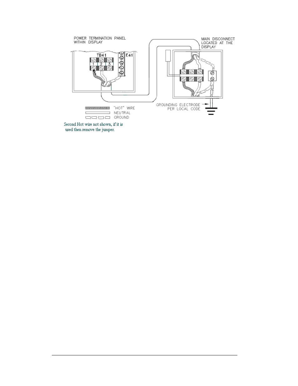
Figure 20: Installation with Ground and Neutral Conductors Provided
Power Connection
Reference Drawings:
Schem, AF-3112-8-32X***-34-Mono-PM.............. Drawing C-200002
Incoming power is connected to the power termination panel. Complete the
following steps to terminate the hot and neutral wires at the termination block within
the display. Refer to Drawing C-200002 for your display.
1. Access the panel by opening the display as described in Section 3.5.
2. Route the power cables through the power conduit in the rear of the display
and to the power term panel.
3. Connect the white neutral wire to termination block, TB41–2.
4. Connect the hot wire to termination block at TB41-1.
5. Connect the green grounding wire to the grounding bus, E41. Refer to
on the previous page.
Main Disconnect
The National Electrical Code requires the use of a lockable power disconnect near
the display. Provide a lockable disconnect switch (knife switch) at the display
location so that all power lines can be completely disconnected. Use a 3-conductor
disconnect so that both hot lines and the neutral can all be disconnected. The main
disconnect should be mounted at or near the point of power supply connection to the
display. A main disconnect is to be provided for each supply circuit to the display.
The disconnecting means must be located in a direct line of sight from the display or
outline lighting that it controls. This requirement provides protection by enabling a
worker to keep the disconnecting means within view while working on the display.
Exception: Disconnecting means that are capable of being locked in the open
position may be located elsewhere.
Electrical Installation
3-8