Modem, Modem -12, Figure 25: modem display layout – Daktronics AF-3112-34-R,A User Manual
Page 32
Modem
Reference Drawings:
System Riser Diagram, Modem Comm. Box............... Drawing A-199218
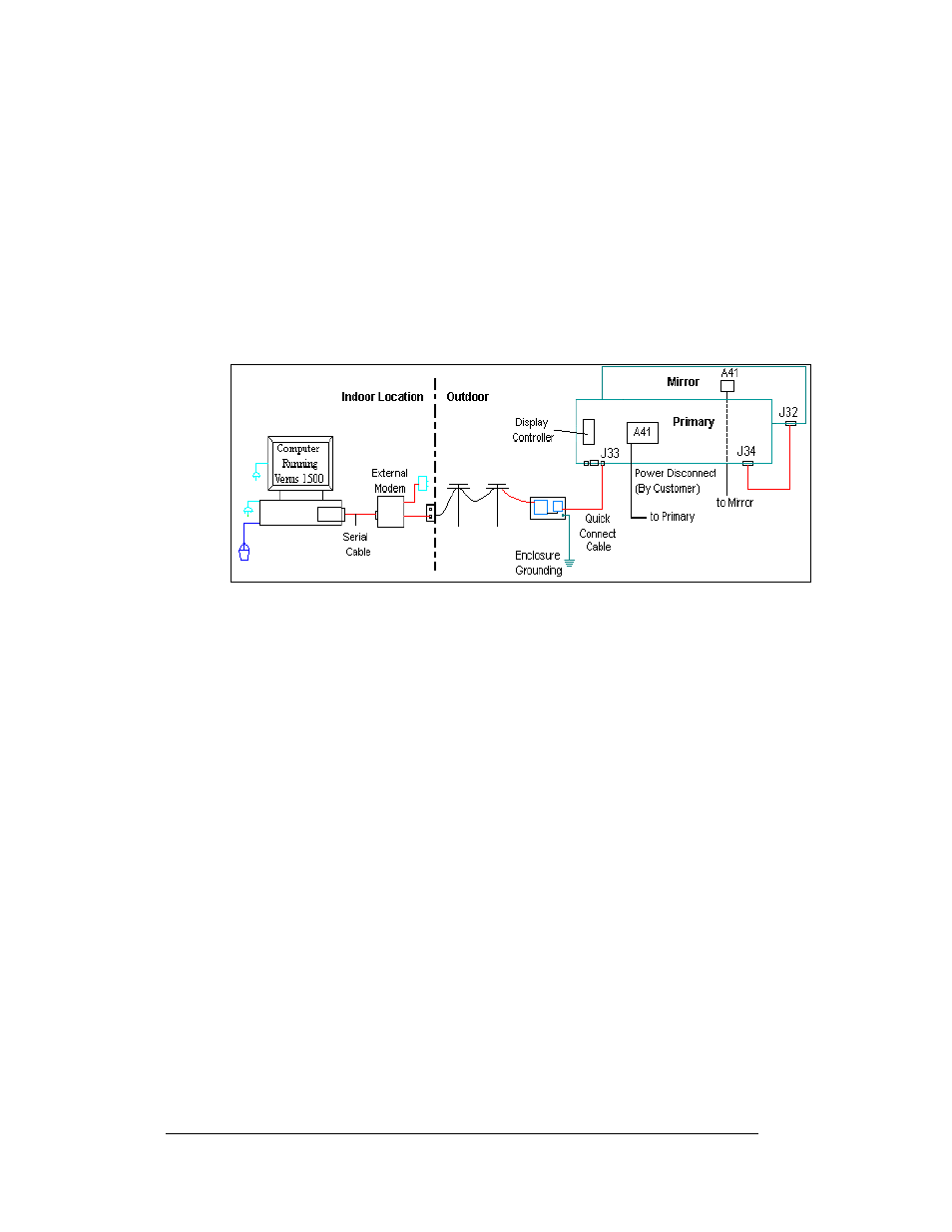
A modem-controlled display requires the use of an internal or external modem at the
computer. The local phone company must provide a dedicated phone line to the
display and identify the colors used for “Tip” and “Ring”. The telephone cable is
terminated to TB2 on the modem in the weather resistant enclosure at the display.
The phone cable must be routed though conduit. Do not run signal and display
power through the same conduit. Refer to Drawing A-199218 and
system layout.
Figure 25: Modem Display Layout
Note: The cable from the enclosure to the display can be routed though conduit, or
should be secured to prevent being pulled loose from the display by weather or
vandalism.
1. Mount the enclosure within 25 feet of the display.
2. Have the phone company route a dedicated phone line to the display and
identify which wires are used for Tip and Ring.
3. The Tip and Ring phone wires will terminate to the modem, as shown in the
modem termination enclosure in
4. Connect the quick connect cable from the enclosure to J33 on the back of
the primary display.
5. Ground the modem enclosure.
Note: The jumper X1 on the controller board must be closed while the display
powers up to recognize that a modem is being used with the display. See
in Section 4 for jumper location.
Electrical Installation
3-12