Appendix b:signal converter, 0a-1127-0237 – wire, Appendix b – Daktronics AF-3020-7.6-R,A User Manual
Page 35: Appendix b: signal converter
Appendix B:
Signal Converter
The following table gives the typical state of the signal converter when the LEDs are either on or off.
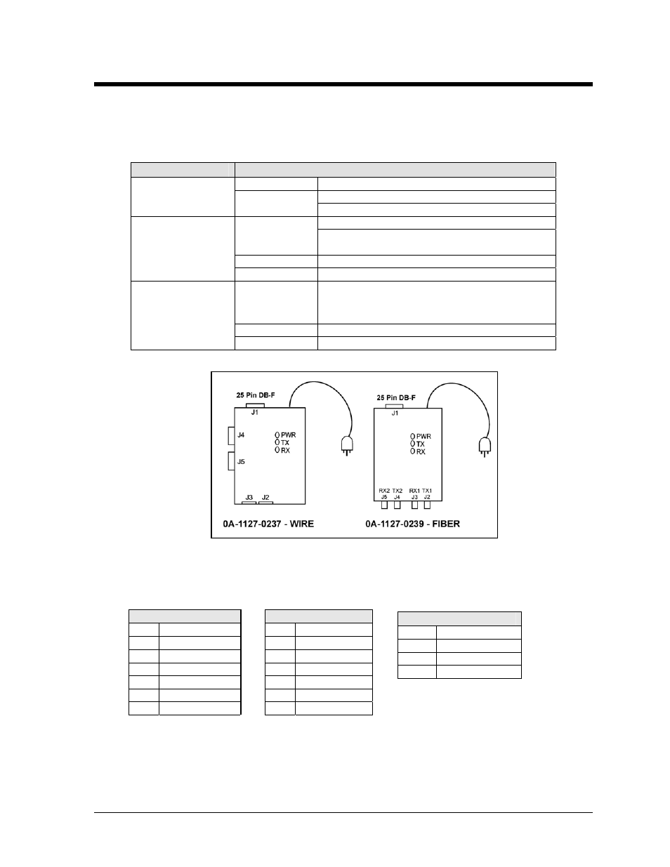
Refer to Figure 19 for an illustration of the signal converters and the locations of the various
components.
LED Indicators
Typical States
ON
Signal Converter (SC) is receiving power.
SC is not receiving power.
PWR
OFF
Internal 1 AMP Fuse is bad.
SC is not connected to a serial port.
ON Steady
(If connected to serial port) Serial port or serial
cable may be bad.
OFF Steady
Normal state, SC is not transmitting data.
TX
Brief Flicker
SC is transmitting data.
ON Steady
Field cabling between SC and display is bad,
connected to display out or terminated
incorrectly.
OFF Steady
Normal state, SC is not receiving data.
RX
Brief Flicker
SC is receiving data.
Figure 21: Signal Converters
0A-1127-0237 – Wire
The following tables list the jack pin-outs for a wire signal converter.
J2 & J3 - RJ/11
J4 & J5 – Phoenix
PIN OPERATION
PIN
OPERATION
1 GND
1 GND
2
TX-N (out)
2
RX-P (in)
3
TX-P (out)
3
RX-N (in)
4
RX-N (in)
4
TX-P (out)
5
RX-P (in)
5
TX-N (out)
6 GND
6 GND
J1 25 Pin DB-F
PIN OPERATION
2 TX-P
(out)
3 RX-P
(in)
7 GND
Loop-Back Test: To perform a loop-back, for testing purposes only, connect the following using
copper conductor jumpers.
Appendix B: Signal Converter
B-1