Conduit, Conduit -2, Figure 9: phoenix connector -2 – Daktronics AF-3020-7.6-R,A User Manual
Page 16: Figure 10: mat-n-lok connector -2, Figure 11: tab connector -2
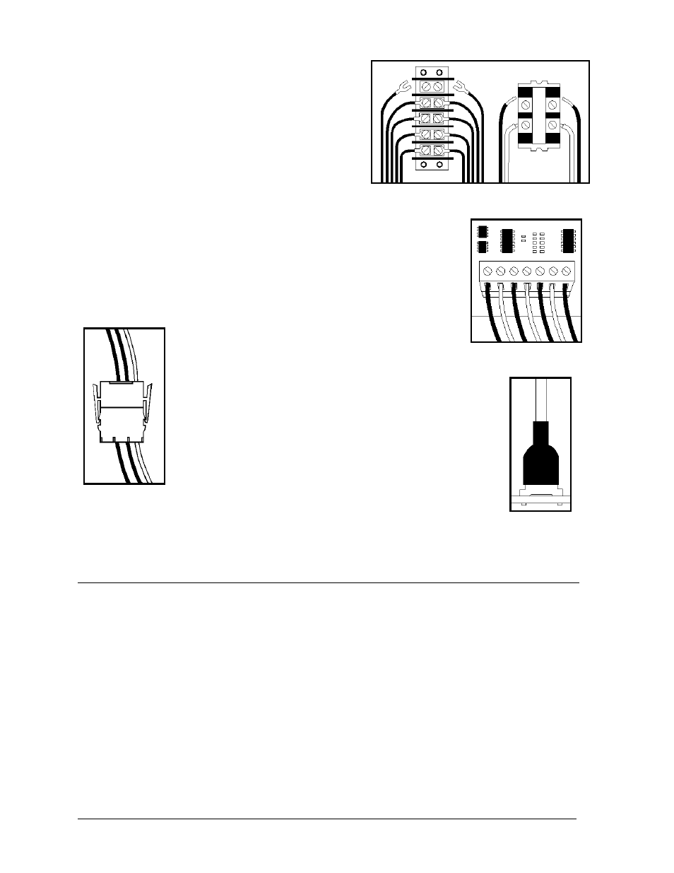
4. Termination Panels & Termination Blocks:
Figure 8: Termination Panel (Left) and
Termination Block (Right)
Termination panels and termination blocks are most
often used to connect internal power and signal wires
to wires of the same type coming into the display
from an external source. Most signal wires will come
with forked connectors crimped to the ends of the
wire. Power wires need to have one-half inch of
insulation stripped from the end of the wire prior to
termination. Tighten all screws firmly to ensure a
good electrical connection. Refer to Figure 8.
5. Phoenix-Style
Connectors:
Electrical Installation
3-2
Phoenix-style connectors, which are usually green, are often used for
signal termination on circuit boards. Refer to Figure 9. One-quarter inch
of insulation must be stripped from the wire prior to termination. To
remove a wire, turn the above screw counter-clockwise to loose the
connectors grip on the wire. To insert a wire, push the bare wire into the
connector and turn the above screw clockwise to lock the wire into place.
6. Mate-n-Lok
™
Connectors:
The Mate-n-Lok connectors found in this display are
white and come in a variety of sizes. Figure 10
illustrates a four-pin Mate-n-Lok connector. To remove the
plug from the jack, squeeze the plastics locking clasps of the
side of the plug and pull it from the jack.
Figure 9: Phoenix
Connector
Figure 10: Mat-
n-Lok
Connector
Figure 11: Tab
Connector
7. Tab
Connectors:
The tab connector, illustrated in Figure 11, is found in most
Daktronics displays. Grab the connector on the plastic
terminal cover when removing. Do not pull it off the tab by
pulling on the wire.
3.2 Conduit
Reference Drawings:
System Riser Diagram (Modem) ........................................................... Drawing A-88426
Power/Signal Termination Panel ........................................................... Drawing A-88427
System Riser Diagram (422) ................................................................. Drawing A-92681
System Riser Diagram, Fiber .............................................................. Drawing A-110559
Power Termination Box ....................................................................... Drawing A-140262
Daktronics does not include the conduit. Possible power and signal entrances are designated by
center punches. Refer to the project specific shop drawing for the placement of the center punches.
Separate conduit must be used to route the following:
·
Power
·
Signal IN wires
·
Signal OUT wires (if signal is required for another display)