Signal termination from computer to display, Rs/232, Rs/422 – Daktronics AF-3020-7.6-R,A User Manual
Page 20: Modem, Signal termination from computer to display -6, Rs/232 -6, Rs/422 -6, Modem -6
3.5
Signal Termination from Computer to Display
Reference Drawings:
System Riser Diagram (Modem) ........................................................... Drawing A-88426
Signal/Power Termination Panel ........................................................... Drawing A-88427
System
Riser
Diagram (422) ................................................................. Drawing A-92681
System
Riser
Diagram (232) ................................................................. Drawing A-96058
Sys. Riser Diag., Fiber ........................................................................ Drawing A-110559
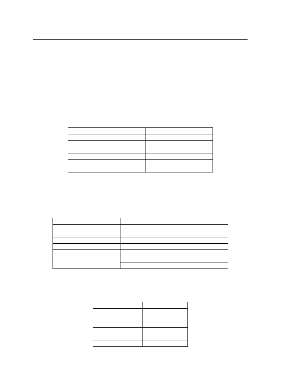
RS/232
One end of the signal cable should be terminated to the 10 position terminal block in the display
labeled “IN RS/232” (TB42). Drawing A-88427 is an example of the termination panels. The
opposite end is terminated at the J-box at the display structure. The laptop PC connects to the J-
box through the serial cable (refer to Drawing A-96058).
J-Box
Field Cabling
Terminal Block (Data In)
Pin 1 (N.C.)
Pin 2 (N.C.)
Pin 2 (RX-P)
Clear
Pin 3 (TX-P)
Pin 3 (GND)
Shield
Pin 4 (GND)
Pin 1 (TX-P)
Black
Pin 5 (RX-P)
Pin 6 (N.C.)
RS/422
One end of the signal cable should be terminated to the 10-position terminal block in the display
labeled “IN RS/422” (TB42). Drawing A-88427 is an example of the termination panel. The
opposite end is terminated at the signal converter (Daktronics part number 0A-1127-0237) in the
control room.
Signal Converter (J4/J5)
Field Cabling
Terminal Block (Data In)
Pin 1 (GND)
Red
Pin 1 (GND)
Pin 2 (RX-P)
Black
Pin 2 (TX-P)
Pin 3 (RX-N)
Brown
Pin 3 (TX-N)
Pin 4 (TX-P)
White
Pin 4 (RX-P)
Pin 5 (TX-N)
Blue
Pin 5 (RX-N)
Green
Pin 6 (GND)
Pin 6 (GND)
Shield (Bare)
N.C.
Modem
Terminate the signal telephone wires to the 10 position terminal block labeled “IN MODEM”
(TB42) as follows:
Telephone Wires
Terminal Block
N.C. Pin
1
N.C. Pin
2
TIP-P Pin
3
Ring-P Pin
4
N.C. Pin
5
N.C. Pin
6
Electrical Installation
3-6