Controller board, Display controller, Leds & jumpers – Daktronics AF-3020-7.6-R,A User Manual
Page 24: Controller board -2, Display controller -2, Leds & jumpers -2
7. Attach the bracket to the mounting panel using the screws, close the sign door and test the
display.
8. The power supply voltage may need to be adjusted to match the voltage setting off the existing
power supplies.
4.4 Controller
Board
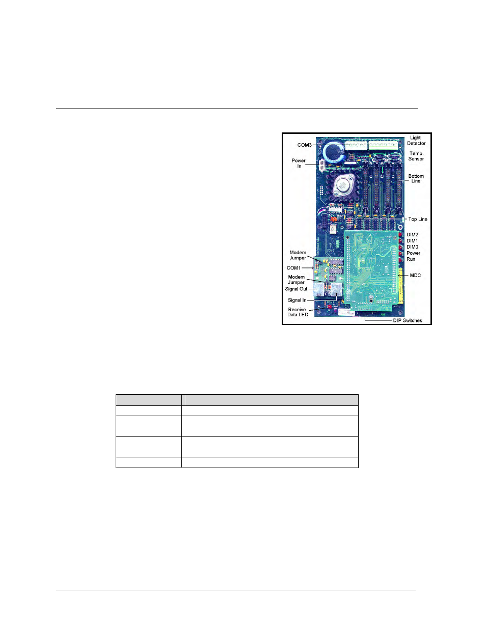
Display Controller
Figure 14: Display Controller
The display controller is the “brains” of the sign. It is
attached to a mounting panel and is in the bottom left
side of each sign.
1. Open the sign as described in Section 4.2.
2. Remove all power and signal connections. “Locked”
connectors are released by squeezing together the
tabs, then carefully pulling them from the jack.
3. Remove the six (6) securing screws and then lift the
controller from the sign.
4. Contact Daktronics Customer Service for the
repair/replacement of the controller (refer to Section
4.11).
5. Follow the above steps in reverse order to install a
new display controller.
LEDs & Jumpers
The controller board contains three DIM, one Power, one
RUN and one Receive Data LEDs.
The controller’s communication module contains two (2) jumpers for a modem system. The
jumpers must jump both pins for a modem system. For all other applications, the jumpers must be
removed.
LED
Normal State
DIM 0, 1, 2
On state dependant on light level
Power
On steady when controller is receiving
10VAC power.
Run
Flashes at rate of once per second when
the controller is running.
Receive Data
Flashes only during data transmission.
4-2
Maintenance & Troubleshooting