Transformer, Communicate accessories, Accessing and replacing the modem – Daktronics AF-3020-7.6-R,A User Manual
Page 26: Fiber board, Leds & jumpers, Transformer -4, Communicate accessories -4, Accessing and replacing the modem -4, Fiber board -4, Leds & jumpers -4
5. Reattach the new circuit board as shown in Drawing A-169332 and the project specific
schematic. Note the orientation of the new circuit board. The photocell must line up with the ½"
circular opening in the front of the display when the assembly is in place.
4.6 Transformer
The transformer is used to provide power to the controller board. It is located in the bottom left corner
(front view) of the display in the power termination box.
4.7 Communicate
Accessories
Accessing and Replacing the Modem
If a modem is included with the display, it is located inside the sign next to
the controller board.
4-4
Maintenance & Troubleshooting
1. To replace a modem, first disconnect the power and signal connections
(Refer to Figure 16 for the location of the power jack).
2. The modem is held in place with four screws. Carefully remove them.
3. Install the new modem, replace the screws and reconnect power and
signal cables.
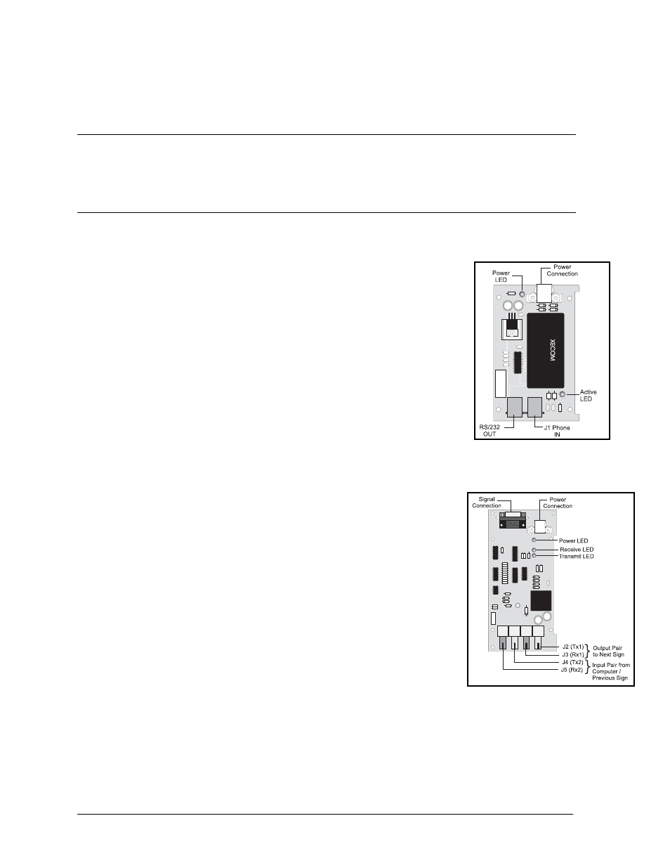
Fiber Board
The fiber module has three LEDs. The power LED (DS1) should remain lit
while power is applied to the module. The receive LED (DS2) will light
when the display fiberboard is accepting signal from the computer
fiberboard. The transmit LED (DS3) will light when the display fiberboard
is sending to the computer fiberboard. In addition, the fiberboard has two incoming fiber
connectors and two outgoing fiber connectors. The fiberboard connects to
the controller board with a small DB9 to RJ11 flipped adaptor and a
straight through RJ11 cable.
Figure 16: Modem
Figure 17: Fiber Optic Board
To replace a fiber optic board:
1. Disconnect the power and signal connections (Refer to Figure 17 for
disconnection of power).
2. The fiber optic board is held in place with four screws. Carefully
remove them.
3. Install the new fiber optic board, replace the screws and reconnect
power and signal cables.
LEDs & Jumpers
The modem module has two (2) LEDs. The power LED should remain lit
while power is applied to the modem. The active LED will light when the
modem is in the process of communicating.
A modem system requires jumpers to be set on the controller board. Refer to LEDs & Jumpers in
Section 4.4 for these jumper settings.