Fiber optic, Signal termination between two (or more) displays, Rs/422 interconnection – Daktronics AF-3020-7.6-R,A User Manual
Page 21: Fiber interconnection, Fiber optic -7, Rs/422 interconnection -7, Fiber interconnection -7
Electrical Installation
3-7
i
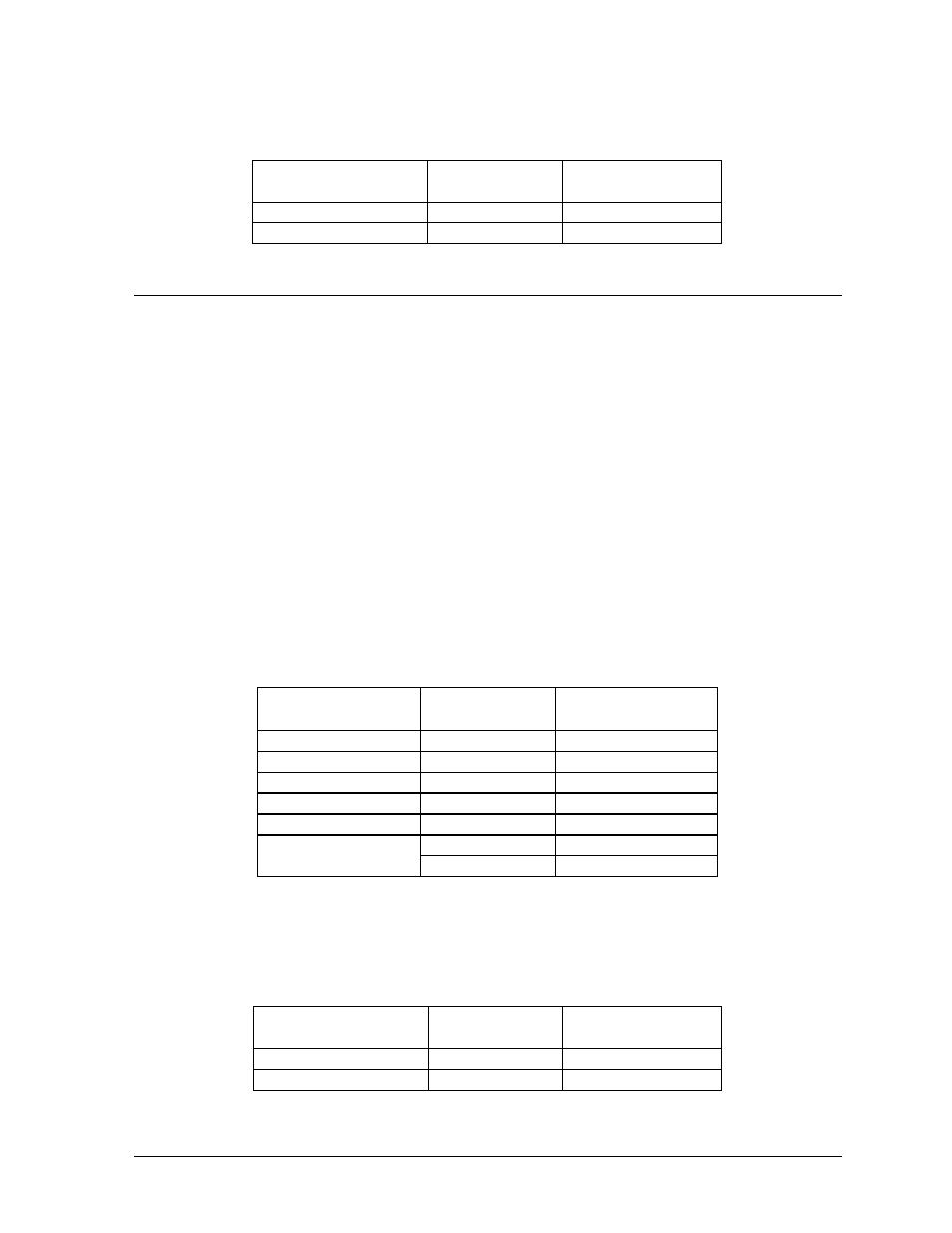
Fiber Opt c
Route conduit and fiber cable from the PC to the left end of the master display. Continue routing
fiber to the controller box. Connect fiber cable from the signal converter of the PC to the fiber
card in the display as described on the following table.
Signal Converter
Data Out (J2 & J3)
Field Cabling
Sign A
Data In (J4 & J5)
J2 (TX1)
J5 (RX2)
J3 (RX1)
J4 (TX2)
3.6
Signal Termination Between Two (or More) Displays
Reference Drawings:
System Riser Diagram (Modem) ........................................................... Drawing A-88426
Signal/Power
Termination Panel ........................................................... Drawing A-88427
System
Riser
Diagram (422) ................................................................. Drawing A-92681
System Riser Diagram (232) ................................................................. Drawing A-96058
System Riser Diagram (Fiber) ............................................................. Drawing A-110559
The sign-to-sign connections are the same for the RS/232 system, RS/422 system and modem system.
These systems use a RS/422 interconnect method as described below in RS/422 Interconnection.
The fiber system can use either a RS/422 interconnect method or fiber interconnect method as
described in RS/422 Interconnection and Fiber Connection.
RS/422 In erconnection
t
This is the most common method of terminating signal between two or more signs. A 6-conductor
cable is used and one end terminates at the “OUT RS/422” 10-position terminal block (TB43) on
the first display. The other end terminates at the “IN RS/422” 10-position terminal block (TB42)
in the second display.
Sign A
Data Out (TB43)
Field Cabling
Sign B
Data In (TB42)
Pin 1 (GND)
Green
Pin 6 (GND)
Pin 2 (Data TX-N)
Blue
Pin 5 (Data RX-N)
Pin 3 (Data TX-P)
White
Pin 4 (Data RX-P)
Pin 4 (Data RX-N)
Brown
Pin 3 (Data TX-N)
Pin 5 (Data RX-P)
Black
Pin 2 (Data TX-P)
Red
Pin 1 (GND)
Pin 6 (GND)
Shield (Bare)
N.C.
Fiber In erconnection
t
A four-conductor fiber cable is used in connecting two or more displays in the Fiber
Interconnection method. Connect the fiber cable to the fiber cards of the display as described on
the following table.
Sign A
Data Out (J2 & J3)
Field Cabling
Sign B
Data In (J4 & J5)
J2 (TX1)
J5 (RX2)
J3 (RX1)
J4 (TX2)