Daktronics DF-1050/1051/1052/1053 User Manual
Page 26
3-8 Electrical
Installation
Manual Control Functions
Reference Drawing:
Enclosure Driver, 4 Col MASC, Wide.......................... Drawing A-191943
System Riser Diagram; DF Display, Parking Lot ........ Drawing A-196787
This is the simplest control
scheme, suitable for low cost
applications where an integrated,
remote control system is not
needed. Using the switches, a
four-digit display can be made to
count from 0 to 9999, blank, or
display ‘OPEN’, or ‘FULL’.
Data sent to the display from
third party software, or from the
DM-100 controller will override
the switch inputs. When the data
signal is removed, the display
will be blank until a switch
closure is sensed.
The signal will be sent using three wires from the switch box to the display. Refer to
Figure 14 and Drawing A-196787 for system layout.
1. The switch box has three pre-attached wires that will need to be connected
to the wires going to the display using wire nuts.
2. Using a 2-pair, 22AWG, cable, connect to the wires going to the display.
The maximum distance is 1000 feet.
3. Use the table and figures to connect the manual switch box to the display.
(Note: The switch box can control the display to either increment or
decrement a number or to switch between open and full.)
As shown on Drawing A-191943,
the terminal block inside the driver
provides connections for 4
switches: INC. (+1), DEC. (-1),
‘OPEN’ and ‘FULL’. Switch
control is implemented by wiring
from these terminals to normally
open switches, as shown on
Drawing A-196787. An optional
switch assembly containing
momentary toggle switches in an
outdoor enclosure is available from
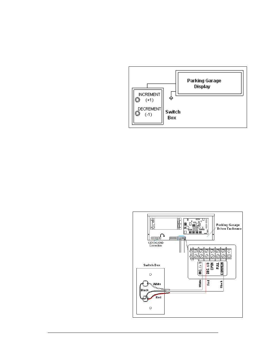
Daktronics (0A-1279-0403).
Figure 14: Manual Control Layout
Figure 15: Manual Control Connections