Daktronics DF-1050/1051/1052/1053 User Manual
Page 22
3-4 Electrical
Installation
The customer's electrician completes the signal termination as shown on the
schematic, Drawing A-191943. Recommended signal conductor is 2-pair, 22 AWG,
stranded with shield (Daktronics part number W-1234), but 18 AWG may be used as
indicated on the drawing. If the sign is to be operated from switches, this wiring may
be done using 22 AWG cable. Shielded cable is recommended if the switch wiring is
run next to other cables that may induce noise in the switch wiring.
Daktronics provides the protocol plug for the signal, and the customer may use
standard DataMaster software or may provide his or her own software.
Current Loop (DataMaster)
Reference Drawing:
Enclosure Driver, 4 Col MASC, Wide.......................... Drawing A-191943
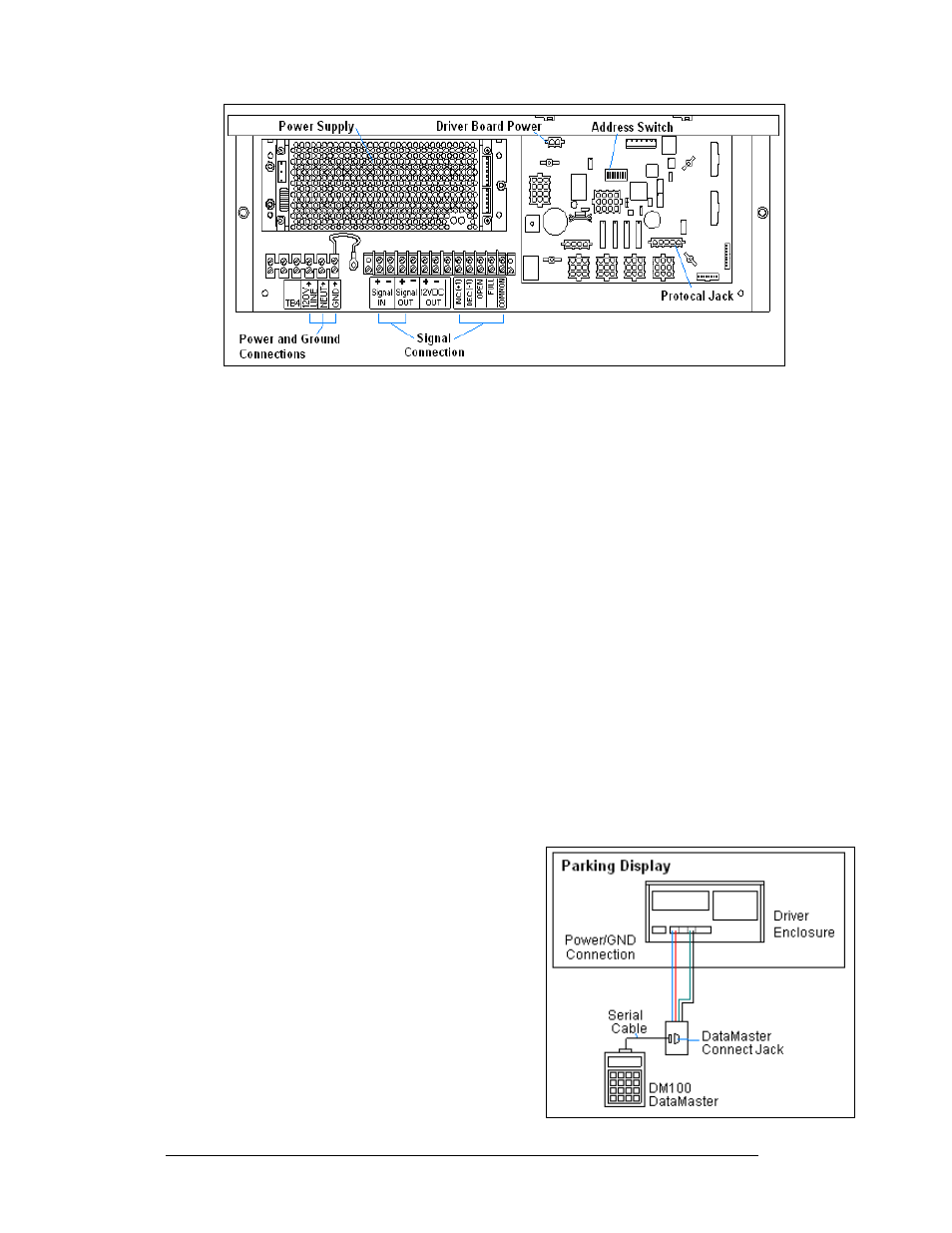
A directly controlled display uses a current loop connection from the j-box at the
display to the driver enclosure in the sign. All the power and signal wiring terminates
at the driver enclosure. The DataMaster hand-held controller receives its power from
the display. The display layout is shown in Figure 8.
Note: The cable from the j-box to the display needs to be routed through conduit or
the display pole to protect it from weather or vandalism.
1. Mount the j-box near the display.
2. Route a 4-conductor cable through conduit
from the j-box to the driver enclosure in the
host display. (Distance limit from the j-box
to the display is 50 ft.)
3. Connect the signal/power cable from the j-
box to the driver enclosure as shown in
Figure 9 and listed in the table. Refer to
Drawing A-191943 for additional
information.
4. Using a DB9M to DB9F serial cable, plug
the DataMaster controller into the j-box
connected to the driver enclosure.
Figure 7: DataMaster Driver Enclosure with 4-Column Driver
Figure 8: Direct, DataMaster Control