Primary – primary (fiber) – Daktronics Fiber Optic Communication User Manual
Page 9
5. See the instructions for the Optional Temperature Sensor in the appendix of
the display manual for connections that need to be made for the temperature
sensor termination.
Primary – Primary Interconnect Cable
Face A – RS422
OUT (TB3)
Field
Cabling
Face B – RS422
IN (TB2)
Pin 1 (GND)
Shield
Pin 6 (GND)
Pin 2 (D2OUT-N)
Red
Pin 5 (D1IN-N)
Pin 3 (D2OUT-P)
Black
Pin 4 (D1IN-P)
Pin 4 (D2IN-N)
Green
Pin 3 (D1OUT-N)
Pin 5 (D2IN-P)
White
Pin 2 (D1OUT-P)
Pin 6 (Shield)
Pin 1 (Shield)
Primary – Primary (Fiber)
If your location requires two displays that cannot be mounted back-to-back, two
primary displays will need to be installed. Those displays can be connected using an
RS422 signal cable or by fiber. In the case of fiber, the following connections will
need to be made:
1. Locate the signal enclosures or open the display, as explained in Section 4.4
of your display manual, to locate the controller panel for these displays.
2. Route the cable through conduit between the enclosures or from the back of
the first primary display to the back of the second primary display. In the
case of internally mounted fiber optic boards, use one of the knockouts for
access, being careful not to damage any internal components
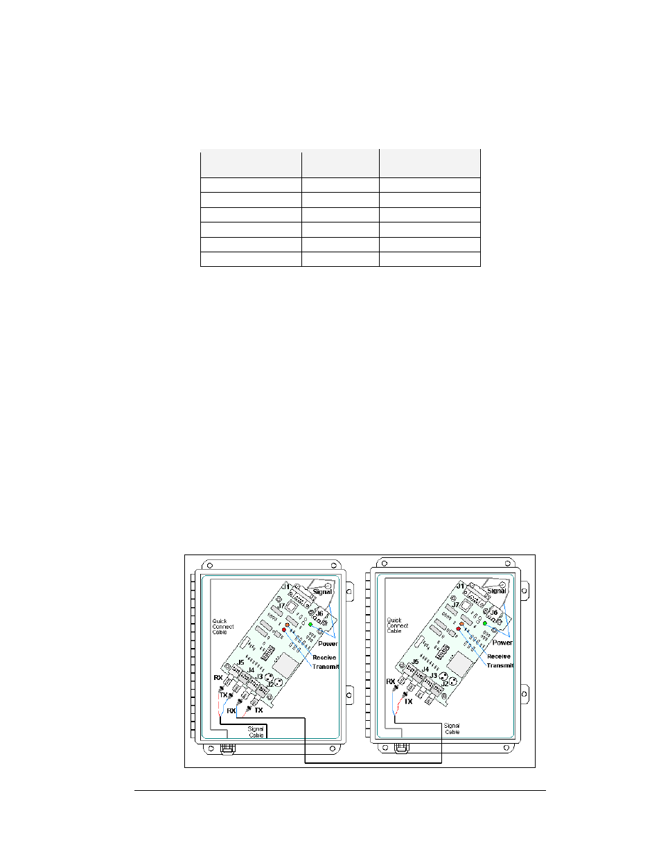
3. Use the fiber cable to connect from transmit and receive of the output jacks
(J2 and J3) to transmit and receive of the input jacks (J4 and J5) on the fiber
optic board. Always connect transmit to receive and receive to transmit as
shown in shown in
and the table.
4. See the instructions for the Optional Temperature Sensor in the appendix of
the display manual for connections that need to be made for the temperature
Figure 7: Fiber Optic Interconnect
Fiber Optic Communication Manual
5