Installation – Daktronics Fiber Optic Communication User Manual
Page 6
Venus 1500: Daktronics designed, Windows
®
based software used to create and edit
messages on the display. Refer to the Venus 1500 Software manual, ED-13530, for
software operation.
Installation
Reference Drawings:
System Riser Diagram, Comm Box, Fiber, QC ........................ Drawing A-211735
A fiber-controlled display requires the following connections:
1. The control computer connects to the signal converter (Daktronics part number 0A-
1127-0256) through a DB9 to DB25 serial cable (W-1249).
2. From the signal converter, fiber cable (Daktronics part number W-1376) is run to the
fiber optic board in the weather resistant enclosure at the display. (In certain cases,
the display may be ordered with the fiber optic board mounted in the display. In
those cases, the terminations will be the same.)
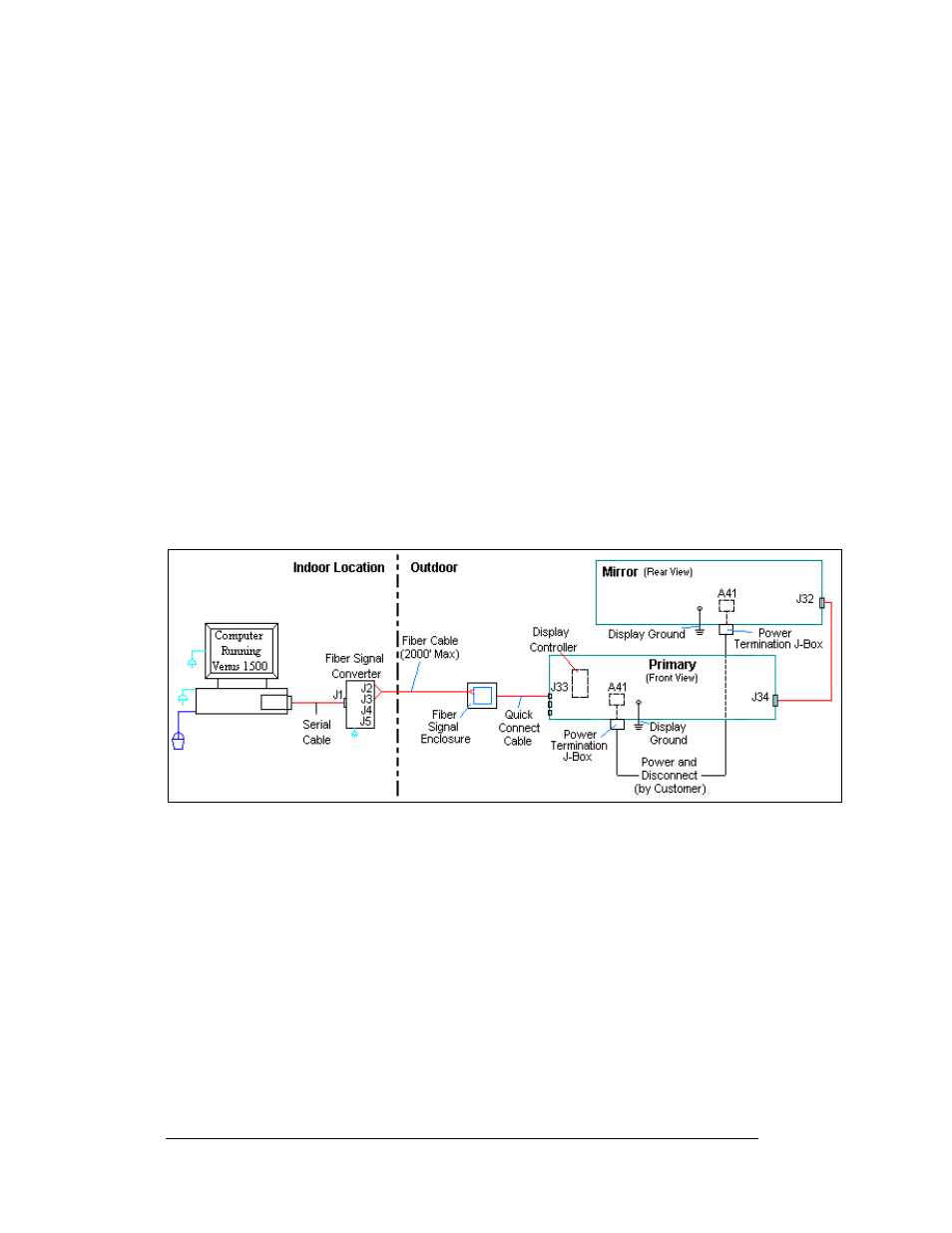
3. When connecting fiber cables, always connect transmit (TX) to receive (RX) and
receive (RX) to transmit (TX). Refer to Figure 2 and Drawing A-211735 for the
system layout.
4. In the case of fiber only, signal and display power can be run through the same
conduit.
Figure 2: Fiber Optic Display Controller
Note: The cable from the signal termination enclosure to the display can be routed though
conduit, through the display pole or should be secured to protect it from weather or
vandalism.
Complete the following steps to connect the signal termination enclosure:
1. Mount the signal termination enclosure within 25 feet of the display.
2. Route fiber optic cable to the enclosure. Two fibers are required.
3. Connect transmit (J4/J2) at the signal converter to receive (J5) in the enclosure and
receive (J5/J3) to transmit (J4). Refer to
and the provided table for fiber
termination locations.
4. Connect the quick connect cable from the enclosure to the primary display. Connect
the cable to the red jack, J33, top, labeled RS 232/RADIO.
Fiber Optic Communication Manual
2