Replacement parts list – Daktronics Fiber Optic Communication User Manual
Page 15
Fiber Optic Communication Manual
11
a. The correct computer COM port is not being used or USB port is not
configured as a “serial” port. (If the Transmit LED flickered this was not
the problem.)
b. Communication problem:
•
The fiber or the ends on the fiber are bad.
c. There was a problem conducting the test:
•
The serial cable to the signal converter is bad or not plugged in.
•
The signal converter is not plugged in.
8. If the words “It appears as if this port has a modem attached”, the modem will
need to be moved or you need to use a different COM port.
After the test is complete:
1. Remove the fiber splice, and reconnect fiber to fiberboard.
2. Run the test again, without the splice, and the test should fail.
3. Use Venus 1500 Display Manager to get status to ensure communication now
works correctly.
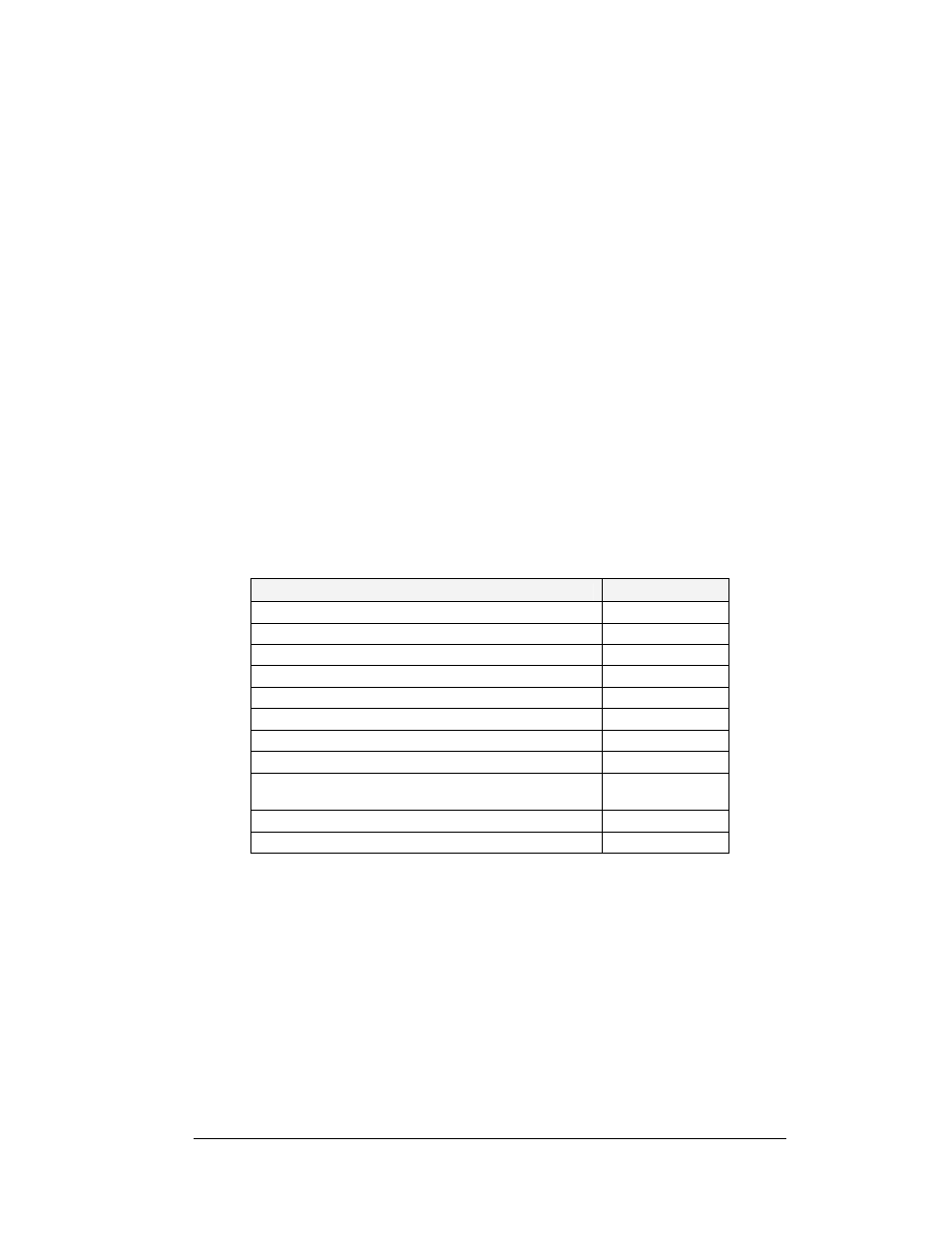
Replacement Parts List
The following table contains some of the items that may need to be replaced over a period of
time. Many of the parts also have their part numbers on labels affixed to them.
To prevent theft, Daktronics recommends purchasing a lockable cabinet to store manuals and
replacement/spare parts.
Part Description
Part Number
Signal Converter, Fiber
0A-1127-0256
Fiber Signal Termination Enclosure (Comm. Box)
0A-1229-0107
Signal Board, RS232 to Fiber, 12V
0P-1127-0024
6-pin M to cable end, 25 ft, Fiber
W-1484
Serial Cable, DB9-F to DB25-M, 6 ft.
W-1249
Four Fiber cable, 62.5/125 grade
W-1376
RJ45, M-M 18” cable, 8-conductor
0A-1229-0054
Plug; 1 pin F, Fiber optic, Splicer
P-1197
Interconnect Cable; 31-pin male to 31-pin male, 6’,
QC
W-1503
Quick Connect Interface, Input, w/Ethernet
0P-1229-2004
31-pin, Quick Connect Input/Output Board
0P-1229-2005