Replacement of the fiber optic board – Daktronics Fiber Optic Communication User Manual
Page 10
sensor termination.
Fiber Optic Board (Primary 1) to Fiber Optic Board (Primary 2)
Fiber Optic Board Field Cabling Fiber Optic Board
J3 Receive (RX2)
(Color varies)
J4 Transmit (TX1)
J2 Transmit (TX2)
(Color varies)
J5 Receive (RX1)
Replacement of the Fiber Optic Board
The following directions are to replace a fiber optic board in the signal termination enclosure
mounted at the display. (In certain cases, the display may have been ordered with the fiber
optic board mounted in the display. The following directions are also true for those
installations.)
1.
To replace a fiber optic board, first disconnect the power and signal connections
(refer to
for connector locations).
2.
The fiber optic board is held in place with four
nuts. Carefully remove them using a 5/16” nut
driver.
Fiber Optic Communication Manual
6
3.
Install the new fiber optic board, replace the nuts
and reconnect power and signal cables.
The fiber optic board has three LEDs.
1. The green power LED (DS1) should remain lit
while power is applied to the fiberboard.
2. The amber receive LED (DS2) will flash when
the display fiber optic board is accepting signal
from the signal converter.
3. The red transmit LED (DS3) will flash when the
fiber optic board is sending to the signal
converter.
In addition, the fiber optic board has several input and
output jacks:
1. J4 and J5 are the two fiber connectors, to which
the fiber signal converter connects. (They can also be used for connecting to another
fiber optic board in a previous primary display if necessary.)
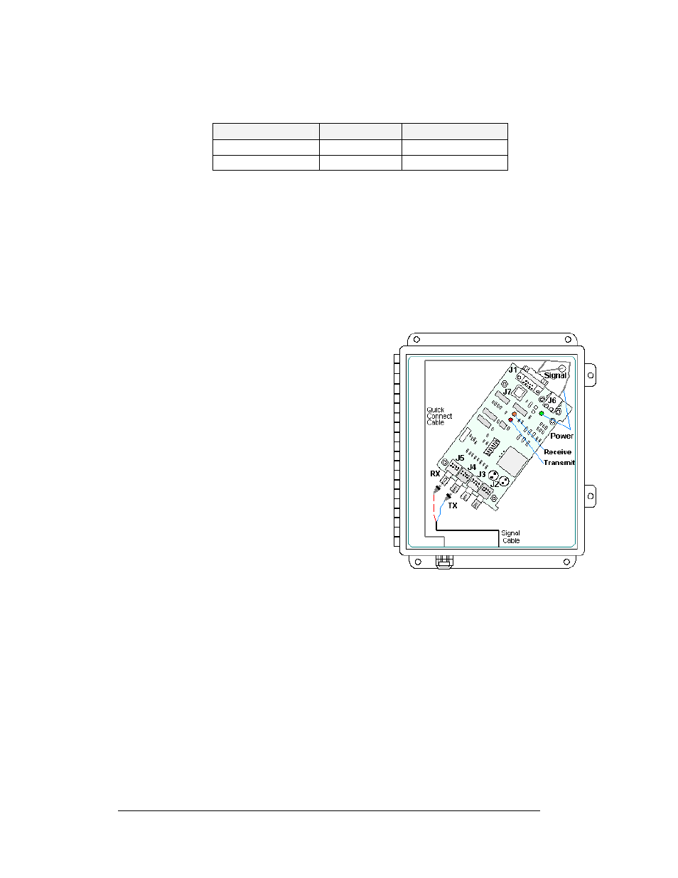
Figure 8: Fiber Optic Board in Enclosure
2. J6 is for the AC power coming from the display.
3. J1, a DB9 connector, that will transfer the signal to the display through the quick
connect cable.
4. J2 and J3 are used only if connected to a second fiberboard in another Primary
display. J7 is not used in the enclosure application.