Primary – primary (rs422) – Daktronics Fiber Optic Communication User Manual
Page 8
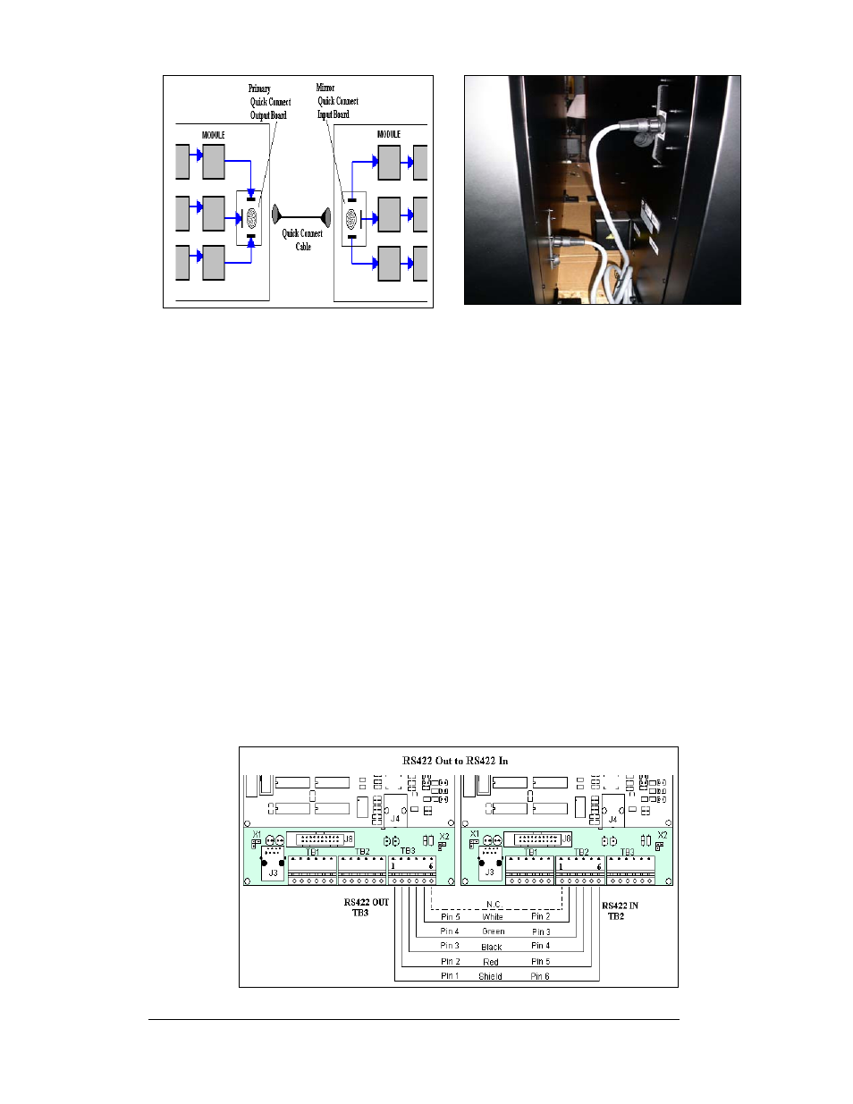
Figure 4: Quick Connect Boards
Figure 5: Display Interconnect
Primary – Primary (RS422)
If your location requires two displays that cannot be mounted back-to-back, two
primary displays will need to be installed. Those displays can be connected using an
RS422 signal cable or by fiber. In the case of RS422, the following connections will
need to be made:
1. Open the display, as explained in Section 4.4 of your display manual, and
locate the controller panel for these displays.
2. Route the cable through conduit from the back of the first primary display
to the back of the second primary display. Use one of the knockouts for
access, being careful not to damage any internal components
3. Use either a 4-pair signal cable or two 4-condutor, shielded cables to
connect both the signal and the temperature sensor information between
displays.
4. The signal cable will connect from TB3 out on the first primary display to
either:
•
A surge board at TB1 in a second primary display
•
(or) To TB2 on the controller in the second primary display.
•
Note: In either case the connections are flipped. See the table and
Drawing B-204771 for connections on both displays.
•
Signal connections between two controllers are shown in
Figure 6: Interconnection from Primary to Primary
Fiber Optic Communication Manual
4