Alternate location installation – Daktronics Fiber Optic Communication User Manual
Page 11
Alternate Location Installation
Reference Drawings:
Schem; Primary Signal, Internal, with QC ................................ Drawing B-206146
Note: If the display was ordered with the fiber optic board internally installed, these
connections have already been completed.
If necessary, the fiber optic board can be moved from the signal termination enclosure and
located in the display. The fiber optic board will be mounted on the standoffs next to the
controller board or in the left end of the display. The following connections will need to be
made for the fiber optic board to operate in the display:
1. Route the fiber through conduit to the back of the display. Use one of the knockouts
for access, being careful not to damage any internal components.
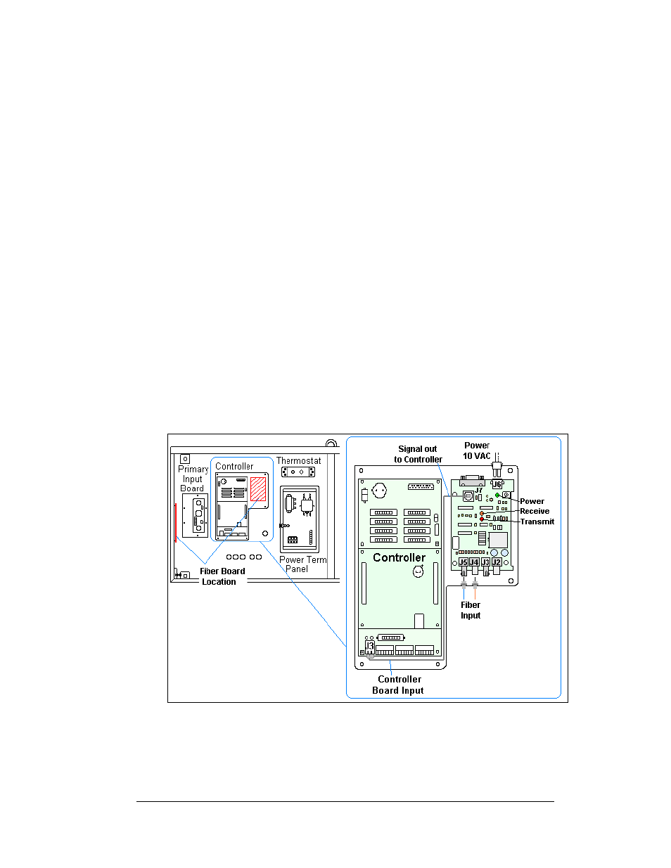
2. Connect two fiber lines of the fiber cable (Daktronics part number W-1376) from the
signal converter to the fiber optic board. Always connect receive on the signal
converter to transmit (J5) on the fiberboard and transmit at the signal converter to
receive (J4) on the fiber optic board.
3. Signal connects from the J7 output on the fiber optic board to J3 on the controller.
Use a straight 8-conductor, RJ45 cable (Daktronics part number 0A-1229-0054) to
make the connection.
4. Using the pre-terminated power cable, provided in the display, connect power from
the transformer (10 VAC) into J6 on the fiberboard.
5. See
and Drawing B-206146 for fiber connections in the display.
Figure 9: Relocating the Fiber Board in the Display
Fiber Optic Communication Manual
7