Rear access, 6 display drivers, Display drivers – Daktronics BA-1518 Multi-Section Outdoor LED Scoreboard User Manual
Page 48: N 6.6 )
42
TNMC & Electronic Caption Troubleshooting & Maintenance
Rear Access
1. To access the internal components from the rear, remove the appropriate rear-access
panel from the display cabinet by loosening all four of the screws.
2. Slide the access panel sideways to the larger part of the keyhole and carefully lift it
off the display cabinet.
Note: Be careful when removing and handling the access panels as internal display
components may still be attached to them.
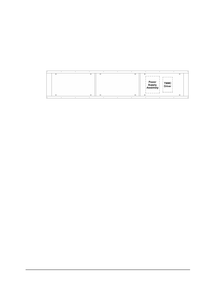
The display driver and primary power supply will always be located behind the first access
panel on the right, when viewing the display from behind. Any additional power supplies are
noted in the appropriate component location drawings.
Note: In displays built before September 2009, the driver is located behind the first access
panel and the primary power supply is located behind the second access panel.
6.6 Display Drivers
Reference Drawings:
Address Table, 129 Through 255 ............................................................ Drawing A-115079
4 Column MASC LED Driver Specifications ............................................ Drawing A-166216
Address Table: Driver- MCAST G2- TNMC Switch ................................. Drawing A-328274
Specifications; Driver, MCAST, 4 Col ...................................................... Drawing A-793970
The display driver receives signal from the control console via a signal surge arrestor card
and sends data to the modules. Refer to Section 6.4 for more information on signal routing.
The driver itself is detailed in Drawing A-793970 in Appendix A. Figure 37 illustrates some
of the primary jacks and switches on the 4 Column MCAST display driver.
The S2 DIP switch is the component for setting the address (switches #1-4). With switches 1-4
off, the address setting for a TNMC is preset at “221”. (There may be other address settings if
the TNMC is used to display messages other than team names.) For electronic captions, the
driver address must be set to “227” (Time Outs Left captions require address “225”). Refer to
Drawing A-328274 in Appendix A for more information on setting the driver address.
Note that the S2 DIP switch also controls Home and Guest display. When the #5 switch is
ON, the TNMC sends guest team information to the matrix display. In the opposite message
center, the switch would be set to OFF, and home information would be displayed.
Figure 36: Display Cabinet Rear Access
- BA-1524 Multi-Section Outdoor LED Scoreboard BA-2013 Multi-Section Outdoor LED Scoreboard BA-3718 Multi-Section Outdoor LED Scoreboard BA-3724 Multi-Section Outdoor LED Scoreboard FB-2018 Multi-Section Outdoor LED Scoreboard FB-2019 Multi-Section Outdoor LED Scoreboard FB-2020 Multi-Section Outdoor LED Scoreboard FB-2021 Multi-Section Outdoor LED Scoreboard FB-2022 Multi-Section Outdoor LED Scoreboard FB-2023 Multi-Section Outdoor LED Scoreboard FB-2024 Multi-Section Outdoor LED Scoreboard FB-2025 Multi-Section Outdoor LED Scoreboard SO-2023 Multi-Section Outdoor LED Scoreboard SO-2022 Multi-Section Outdoor LED Scoreboard SO-2021 Multi-Section Outdoor LED Scoreboard SO-2019 Multi-Section Outdoor LED Scoreboard SO-2018 Multi-Section Outdoor LED Scoreboard SO-2011 Multi-Section Outdoor LED Scoreboard MS-2918 Multi-Section Outdoor LED Scoreboard MS-2009 Multi-Section Outdoor LED Scoreboard FB-3010 Multi-Section Outdoor LED Scoreboard FB-2027 Multi-Section Outdoor LED Scoreboard FB-2026 Multi-Section Outdoor LED Scoreboard BA-2001 LED Baseball Scoreboard BA-2008 LED Baseball Scoreboard BA-2018 LED Baseball Scoreboard BA-2009 LED Baseball Scoreboard BA-2002 LED Baseball Scoreboard FB-2351 Multi-Section LED Football Scoreboard FB-2352 Multi-Section LED Football Scoreboard FB-2353 Multi-Section LED Football Scoreboard FB-2354 Multi-Section LED Football Scoreboard FB-2355 Multi-Section LED Football Scoreboard FB-2356 Multi-Section LED Football Scoreboard FB-2357 Multi-Section LED Football Scoreboard FB-2358 Multi-Section LED Football Scoreboard TN-2016 Single-Court Outdoor LED Tennis Scoreboard TN-2601 Single-Court Outdoor LED Tennis Scoreboard TN-2603 Single-Court Outdoor LED Tennis Scoreboard TN-2604 Single-Court Outdoor LED Tennis Scoreboard TN-2605 Single-Court Outdoor LED Tennis Scoreboard TN-2606 Single-Court Outdoor LED Tennis Scoreboard TN-2607 Single-Court Outdoor LED Tennis Scoreboard TN-2601 Outdoor LED Tennis Scoreboard TN-2603 Outdoor LED Tennis Scoreboard TN-2604 Outdoor LED Tennis Scoreboard TN-2605 Outdoor LED Tennis Scoreboard TN-2606 Outdoor LED Tennis Scoreboard TN-2607 Outdoor LED Tennis Scoreboard TN-2650 Outdoor LED Tennis Scoreboard TN-2651 Outdoor LED Tennis Scoreboard TN-2652 Outdoor LED Tennis Scoreboard TN-2653 Outdoor LED Tennis Scoreboard TN-2654 Outdoor LED Tennis Scoreboard TN-2655 Outdoor LED Tennis Scoreboard TN-2656 Outdoor LED Tennis Scoreboard TN-2657 Outdoor LED Tennis Scoreboard