3 scoreboard mounting, Scoreboard mounting – Daktronics BA-1518 Multi-Section Outdoor LED Scoreboard User Manual
Page 19
Mechanical Installation
13
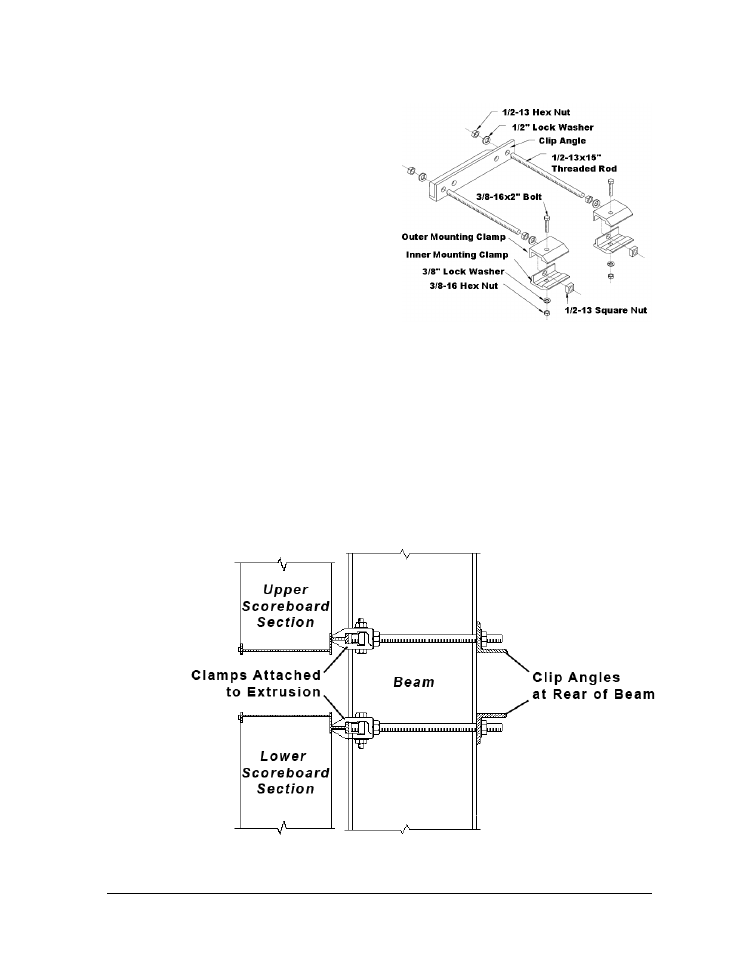
3.3 Scoreboard Mounting
Mounting hardware includes inner and
outer mounting clamps; clip angles;
1
/
2
-13 x
15" threaded rods;
3
/
8
-16 x 2" bolts, hex nuts
and lock washers; and
1
/
2
" square nuts, hex
nuts, and lock washers. Refer to Figure 6 or
Drawing A-308051 in Appendix A. Each
section of the scoreboard attaches at the top
and the bottom to every beam.
Note: The threaded rods do not pass
through the flanges of the beams, but
instead run along both sides.
1. Using
3
/
8
" bolts, loosely attach the
inner and outer mounting clamps to
the rear flanges of the scoreboard.
Measure the beam spacing and position the clamps to fit on either side of the beams.
2. Insert a
1
/
2
" square nut into each mounting clamp. Screw a threaded rod into each of
the nuts from the rear.
3. Position the scoreboard at the front of the beams with the threaded rods extending
from the rear of the clamps, straddling the beams. Raise the scoreboard section to the
desired height.
4. Slide clip angles over the ends of the rods and loosely install the washers and nuts.
5. Make final adjustments in the positioning of the scoreboard. Tighten the
3
/
8
" bolts in
the mounting clamps.
6. Make sure that the threaded rods are perpendicular to the scoreboard, and tighten all
of the
1
/
2
" hex nuts (Figure 7).
Figure 6: Mounting Hardware
Figure 7: Clamp Mounting Method, Side View
- BA-1524 Multi-Section Outdoor LED Scoreboard BA-2013 Multi-Section Outdoor LED Scoreboard BA-3718 Multi-Section Outdoor LED Scoreboard BA-3724 Multi-Section Outdoor LED Scoreboard FB-2018 Multi-Section Outdoor LED Scoreboard FB-2019 Multi-Section Outdoor LED Scoreboard FB-2020 Multi-Section Outdoor LED Scoreboard FB-2021 Multi-Section Outdoor LED Scoreboard FB-2022 Multi-Section Outdoor LED Scoreboard FB-2023 Multi-Section Outdoor LED Scoreboard FB-2024 Multi-Section Outdoor LED Scoreboard FB-2025 Multi-Section Outdoor LED Scoreboard SO-2023 Multi-Section Outdoor LED Scoreboard SO-2022 Multi-Section Outdoor LED Scoreboard SO-2021 Multi-Section Outdoor LED Scoreboard SO-2019 Multi-Section Outdoor LED Scoreboard SO-2018 Multi-Section Outdoor LED Scoreboard SO-2011 Multi-Section Outdoor LED Scoreboard MS-2918 Multi-Section Outdoor LED Scoreboard MS-2009 Multi-Section Outdoor LED Scoreboard FB-3010 Multi-Section Outdoor LED Scoreboard FB-2027 Multi-Section Outdoor LED Scoreboard FB-2026 Multi-Section Outdoor LED Scoreboard BA-2001 LED Baseball Scoreboard BA-2008 LED Baseball Scoreboard BA-2018 LED Baseball Scoreboard BA-2009 LED Baseball Scoreboard BA-2002 LED Baseball Scoreboard FB-2351 Multi-Section LED Football Scoreboard FB-2352 Multi-Section LED Football Scoreboard FB-2353 Multi-Section LED Football Scoreboard FB-2354 Multi-Section LED Football Scoreboard FB-2355 Multi-Section LED Football Scoreboard FB-2356 Multi-Section LED Football Scoreboard FB-2357 Multi-Section LED Football Scoreboard FB-2358 Multi-Section LED Football Scoreboard TN-2016 Single-Court Outdoor LED Tennis Scoreboard TN-2601 Single-Court Outdoor LED Tennis Scoreboard TN-2603 Single-Court Outdoor LED Tennis Scoreboard TN-2604 Single-Court Outdoor LED Tennis Scoreboard TN-2605 Single-Court Outdoor LED Tennis Scoreboard TN-2606 Single-Court Outdoor LED Tennis Scoreboard TN-2607 Single-Court Outdoor LED Tennis Scoreboard TN-2601 Outdoor LED Tennis Scoreboard TN-2603 Outdoor LED Tennis Scoreboard TN-2604 Outdoor LED Tennis Scoreboard TN-2605 Outdoor LED Tennis Scoreboard TN-2606 Outdoor LED Tennis Scoreboard TN-2607 Outdoor LED Tennis Scoreboard TN-2650 Outdoor LED Tennis Scoreboard TN-2651 Outdoor LED Tennis Scoreboard TN-2652 Outdoor LED Tennis Scoreboard TN-2653 Outdoor LED Tennis Scoreboard TN-2654 Outdoor LED Tennis Scoreboard TN-2655 Outdoor LED Tennis Scoreboard TN-2656 Outdoor LED Tennis Scoreboard TN-2657 Outdoor LED Tennis Scoreboard