4 signal connection, Fiber optic, Multiple driver connections – Daktronics BA-1518 Multi-Section Outdoor LED Scoreboard User Manual
Page 27: 5 power/signal connections between sections, Signal connection, Power/signal connections between sections
Electrical Installation
21
4.4 Signal Connection
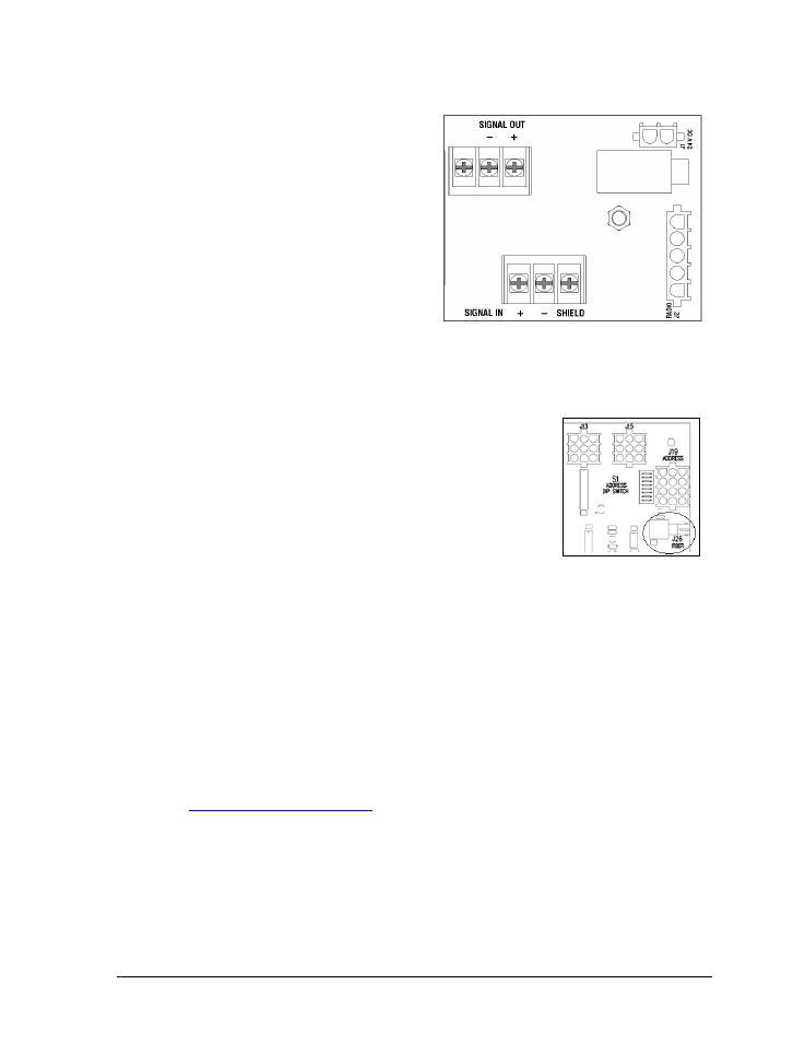
For wired setups, route signal cable through
the conduit knockout on the rear of the
scoreboard to the signal surge arrestor card
(Figure 15), located just above the power
termination block in the driver enclosure.
At the SIGNAL IN terminal block, connect
the red signal wire to the positive terminal
and the black wire to the negative terminal.
Note: Be sure to properly connect the
shield (silver) wire to the SHIELD
terminal.
For signal cable, Daktronics recommends, as a minimum, single-pair, shielded cable, 22 AWG
(part number W-1077). Two-pair shielded cable (part number W-1234) is preferred.
Fiber Optic
Another common signal communication method is fiber optic
cabling. A minimum cabling of multi-mode, 62.5/125 um, and
2-core fiber cable is recommended (part number W-1242).
See Figure 16 for the location of the fiber connector on a 16-
column driver. This method requires a signal converter between
the All Sport console‟s scoreboard output and the fiber optic cable
(not provided by Daktronics).
Multiple Driver Connections
Some models in the multi-section outdoor scoreboard line require multiple drivers in each
scoreboard section, and use a master/slave driver system. Master and slave drivers function
identically, but slave units lack the power termination block and signal surge suppression
card. When one section has multiple drivers, they simply plug into one another, and this is
done at the factory. Drivers between sections, however, require additional on-site connection
as described in Section 4.5.
Note: Scoreboards capable of displaying speed of pitch (SOP) have an additional master
driver. These models also require a separate signal connection (either wired or radio)
from a dedicated speed of pitch All Sport 5000 console. Refer to the Baseball Speed of
Pitch Systems Configuration Manual (ED-12224), available online at
for more information about setting up an SOP system.
4.5 Power/Signal Connections Between Sections
Most multi-section outdoor scoreboards use a single power/signal interconnect cable
between a driver in the upper section and a driver in the lower section (Figure 17).
It is common for the top driver to be located behind the right-most HOME score digit with
the bottom driver located behind the right-most digit of the left-most set of digits. Refer to the
component location drawings in Appendix A for exact driver locations.
Figure 15: Signal Surge Arrestor Card
Figure 16: Driver Fiber
Connection Location
- BA-1524 Multi-Section Outdoor LED Scoreboard BA-2013 Multi-Section Outdoor LED Scoreboard BA-3718 Multi-Section Outdoor LED Scoreboard BA-3724 Multi-Section Outdoor LED Scoreboard FB-2018 Multi-Section Outdoor LED Scoreboard FB-2019 Multi-Section Outdoor LED Scoreboard FB-2020 Multi-Section Outdoor LED Scoreboard FB-2021 Multi-Section Outdoor LED Scoreboard FB-2022 Multi-Section Outdoor LED Scoreboard FB-2023 Multi-Section Outdoor LED Scoreboard FB-2024 Multi-Section Outdoor LED Scoreboard FB-2025 Multi-Section Outdoor LED Scoreboard SO-2023 Multi-Section Outdoor LED Scoreboard SO-2022 Multi-Section Outdoor LED Scoreboard SO-2021 Multi-Section Outdoor LED Scoreboard SO-2019 Multi-Section Outdoor LED Scoreboard SO-2018 Multi-Section Outdoor LED Scoreboard SO-2011 Multi-Section Outdoor LED Scoreboard MS-2918 Multi-Section Outdoor LED Scoreboard MS-2009 Multi-Section Outdoor LED Scoreboard FB-3010 Multi-Section Outdoor LED Scoreboard FB-2027 Multi-Section Outdoor LED Scoreboard FB-2026 Multi-Section Outdoor LED Scoreboard BA-2001 LED Baseball Scoreboard BA-2008 LED Baseball Scoreboard BA-2018 LED Baseball Scoreboard BA-2009 LED Baseball Scoreboard BA-2002 LED Baseball Scoreboard FB-2351 Multi-Section LED Football Scoreboard FB-2352 Multi-Section LED Football Scoreboard FB-2353 Multi-Section LED Football Scoreboard FB-2354 Multi-Section LED Football Scoreboard FB-2355 Multi-Section LED Football Scoreboard FB-2356 Multi-Section LED Football Scoreboard FB-2357 Multi-Section LED Football Scoreboard FB-2358 Multi-Section LED Football Scoreboard TN-2016 Single-Court Outdoor LED Tennis Scoreboard TN-2601 Single-Court Outdoor LED Tennis Scoreboard TN-2603 Single-Court Outdoor LED Tennis Scoreboard TN-2604 Single-Court Outdoor LED Tennis Scoreboard TN-2605 Single-Court Outdoor LED Tennis Scoreboard TN-2606 Single-Court Outdoor LED Tennis Scoreboard TN-2607 Single-Court Outdoor LED Tennis Scoreboard TN-2601 Outdoor LED Tennis Scoreboard TN-2603 Outdoor LED Tennis Scoreboard TN-2604 Outdoor LED Tennis Scoreboard TN-2605 Outdoor LED Tennis Scoreboard TN-2606 Outdoor LED Tennis Scoreboard TN-2607 Outdoor LED Tennis Scoreboard TN-2650 Outdoor LED Tennis Scoreboard TN-2651 Outdoor LED Tennis Scoreboard TN-2652 Outdoor LED Tennis Scoreboard TN-2653 Outdoor LED Tennis Scoreboard TN-2654 Outdoor LED Tennis Scoreboard TN-2655 Outdoor LED Tennis Scoreboard TN-2656 Outdoor LED Tennis Scoreboard TN-2657 Outdoor LED Tennis Scoreboard