Section 3: mechanical installation, 1 footings & beams, 2 lifting the scoreboard – Daktronics BA-1518 Multi-Section Outdoor LED Scoreboard User Manual
Page 17: Section 3, Mechanical installation, Footings & beams, Lifting the scoreboard
Mechanical Installation
11
Section 3:
Mechanical Installation
Mechanical installation consists of installing concrete footing and steel beams and mounting the
scoreboard and accompanying ad panels to the beams.
3.1 Footings & Beams
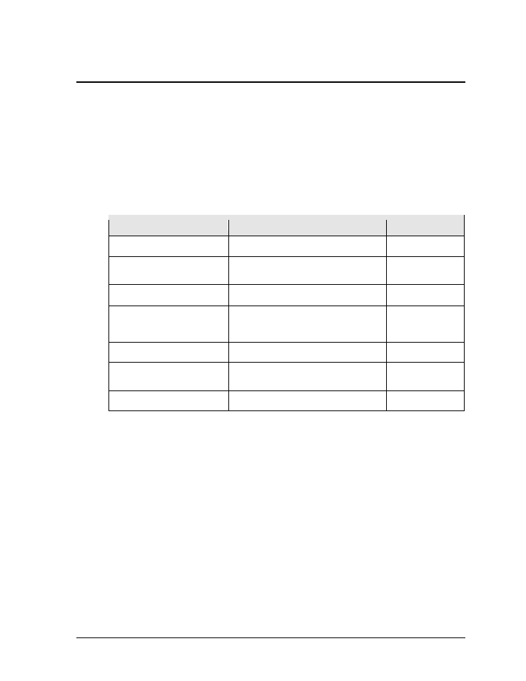
The installation specification drawings listed in Appendix A show the recommended number
of beams and spacing between them. The drawings also indicate the size of beams required to
support the scoreboard at different heights and at various wind speeds. Use the following
table to determine which drawings provide the installation specifications for each model:
Models
Drawing Title
Number
BA-1518, BA-1524, MS-2918
16' Width Scoreboard Installation Specs
A-298975
FB-2018, FB-2019, FB-2020,
FB 3010, SO-2018, SO-2019
18' Width Scoreboard Installation Specs
A-302416
SO-2011
20' Width Scoreboard Installation Specs.
A-303616
FB-2021, FB-2022, FB-2023,
MS-2009, SO-2021, SO-2022,
SO-2023
25' Width Scoreboard Installation Specs
A-316750
BA-3718
28' Width Scoreboard Installation Specs
A-316971
FB-2024; FB-2025, FB-2026,
FB-2027
32' Width Scoreboard Installation Specs
A-317264
BA-3724, BA-2013
Installation Specifications, BA-3724
A-126445
The column and footing size dimensions are to assist with estimating installation costs. They
are estimates only and are not intended for actual construction purposes. Be sure that the
installation complies with local building codes and is suitable for the particular soil and wind
conditions. The columns, footings, and all connection details must be designed and certified
by a professional engineer licensed to practice in the state of the scoreboard installation.
Note: Daktronics does not assume any liability for any installation derived from the
information provided in this manual or installations designed and installed by others.
3.2 Lifting the Scoreboard
Larger scoreboard sections and message centers are shipped equipped with eyebolts used to
lift them. The eyebolts are located along the top of the cabinet for each scoreboard or
scoreboard section. Daktronics scoreboards use
1
/
2
" and
5
/
8
" shoulder-type eyebolts mounted
to a
1
/
8
" aluminum plate or steel nut plate.
Daktronics strongly recommends using a spreader bar, or lifting bar, to lift the display.
Spreader bars ensure the force on the eyebolts remains straight up, minimizing lifting stress.
- BA-1524 Multi-Section Outdoor LED Scoreboard BA-2013 Multi-Section Outdoor LED Scoreboard BA-3718 Multi-Section Outdoor LED Scoreboard BA-3724 Multi-Section Outdoor LED Scoreboard FB-2018 Multi-Section Outdoor LED Scoreboard FB-2019 Multi-Section Outdoor LED Scoreboard FB-2020 Multi-Section Outdoor LED Scoreboard FB-2021 Multi-Section Outdoor LED Scoreboard FB-2022 Multi-Section Outdoor LED Scoreboard FB-2023 Multi-Section Outdoor LED Scoreboard FB-2024 Multi-Section Outdoor LED Scoreboard FB-2025 Multi-Section Outdoor LED Scoreboard SO-2023 Multi-Section Outdoor LED Scoreboard SO-2022 Multi-Section Outdoor LED Scoreboard SO-2021 Multi-Section Outdoor LED Scoreboard SO-2019 Multi-Section Outdoor LED Scoreboard SO-2018 Multi-Section Outdoor LED Scoreboard SO-2011 Multi-Section Outdoor LED Scoreboard MS-2918 Multi-Section Outdoor LED Scoreboard MS-2009 Multi-Section Outdoor LED Scoreboard FB-3010 Multi-Section Outdoor LED Scoreboard FB-2027 Multi-Section Outdoor LED Scoreboard FB-2026 Multi-Section Outdoor LED Scoreboard BA-2001 LED Baseball Scoreboard BA-2008 LED Baseball Scoreboard BA-2018 LED Baseball Scoreboard BA-2009 LED Baseball Scoreboard BA-2002 LED Baseball Scoreboard FB-2351 Multi-Section LED Football Scoreboard FB-2352 Multi-Section LED Football Scoreboard FB-2353 Multi-Section LED Football Scoreboard FB-2354 Multi-Section LED Football Scoreboard FB-2355 Multi-Section LED Football Scoreboard FB-2356 Multi-Section LED Football Scoreboard FB-2357 Multi-Section LED Football Scoreboard FB-2358 Multi-Section LED Football Scoreboard TN-2016 Single-Court Outdoor LED Tennis Scoreboard TN-2601 Single-Court Outdoor LED Tennis Scoreboard TN-2603 Single-Court Outdoor LED Tennis Scoreboard TN-2604 Single-Court Outdoor LED Tennis Scoreboard TN-2605 Single-Court Outdoor LED Tennis Scoreboard TN-2606 Single-Court Outdoor LED Tennis Scoreboard TN-2607 Single-Court Outdoor LED Tennis Scoreboard TN-2601 Outdoor LED Tennis Scoreboard TN-2603 Outdoor LED Tennis Scoreboard TN-2604 Outdoor LED Tennis Scoreboard TN-2605 Outdoor LED Tennis Scoreboard TN-2606 Outdoor LED Tennis Scoreboard TN-2607 Outdoor LED Tennis Scoreboard TN-2650 Outdoor LED Tennis Scoreboard TN-2651 Outdoor LED Tennis Scoreboard TN-2652 Outdoor LED Tennis Scoreboard TN-2653 Outdoor LED Tennis Scoreboard TN-2654 Outdoor LED Tennis Scoreboard TN-2655 Outdoor LED Tennis Scoreboard TN-2656 Outdoor LED Tennis Scoreboard TN-2657 Outdoor LED Tennis Scoreboard