Setting the driver address, Multiple drivers, 8 power supplies – Daktronics BA-1518 Multi-Section Outdoor LED Scoreboard User Manual
Page 37: Power supplies, N 5.8 )
Scoreboard Troubleshooting
31
5. Carefully lift the driver from the display and place it on a clean, flat surface.
6. Position a new driver over the screws and tighten the nuts.
7. Reconnect all power/signal connectors.
Note: The connectors are keyed and will attach in one way only. Do not attempt to
force the connections.
8. Ensure the driver is set to the correct address (refer to Setting the Driver Address).
9. Close and secure the digit panel, then power up and test the scoreboard to see if
changing the driver has resolved the problem.
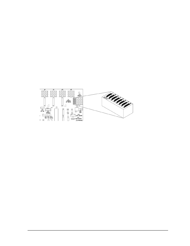
Setting the Driver Address
Since the same LED drivers can be used for many scoreboard models, each driver must be set
to receive the correct signal input, or address, for the model being used. Addresses are set
through the S1 dip switch on the driver (Figure 24) using a pen or small, pointed object.
Refer to the specifications table in Section 2 to determine the correct address setting of the
driver(s) in a particular scoreboard model and see Drawing A-290261 in Appendix A for
addressing information for driver addresses 1 – 128.
Another method of setting the driver address using the J19 address plug is available. This
address is set with jumper wires in a 12-pin plug which mates with a jack on the driver. Refer
to Drawing A-115078 for a listing of the wire/pin connections for driver addresses 1 – 128.
When using an address plug, it will not be possible to set the address with the S1 dip switch.
Multiple Drivers
Scoreboards with multiple drivers operate using a master/slave driver configuration. If it
appears as though only a certain group of digits on the scoreboard is not functioning, there
may be a problem with the slave driver(s) or the power/signal connection from the other
driver(s). Refer to Section 4.5 for more information about these connections.
5.8 Power Supplies
Scoreboards with 16-column driver enclosures require a dual 150 W power supply assembly.
All scoreboards with white digits (except FB-3010, MS-2918, & SO-2011) will also have at least
one 1000 W power supply in addition to, or in place of, the power supplies in the driver
enclosure. The 1000 W power supplies are located in a separate enclosure. If a certain group of
digits is not lighting up, the power supply they are all connected to may need to be replaced.
Figure 24: Driver Address Dip Switch
- BA-1524 Multi-Section Outdoor LED Scoreboard BA-2013 Multi-Section Outdoor LED Scoreboard BA-3718 Multi-Section Outdoor LED Scoreboard BA-3724 Multi-Section Outdoor LED Scoreboard FB-2018 Multi-Section Outdoor LED Scoreboard FB-2019 Multi-Section Outdoor LED Scoreboard FB-2020 Multi-Section Outdoor LED Scoreboard FB-2021 Multi-Section Outdoor LED Scoreboard FB-2022 Multi-Section Outdoor LED Scoreboard FB-2023 Multi-Section Outdoor LED Scoreboard FB-2024 Multi-Section Outdoor LED Scoreboard FB-2025 Multi-Section Outdoor LED Scoreboard SO-2023 Multi-Section Outdoor LED Scoreboard SO-2022 Multi-Section Outdoor LED Scoreboard SO-2021 Multi-Section Outdoor LED Scoreboard SO-2019 Multi-Section Outdoor LED Scoreboard SO-2018 Multi-Section Outdoor LED Scoreboard SO-2011 Multi-Section Outdoor LED Scoreboard MS-2918 Multi-Section Outdoor LED Scoreboard MS-2009 Multi-Section Outdoor LED Scoreboard FB-3010 Multi-Section Outdoor LED Scoreboard FB-2027 Multi-Section Outdoor LED Scoreboard FB-2026 Multi-Section Outdoor LED Scoreboard BA-2001 LED Baseball Scoreboard BA-2008 LED Baseball Scoreboard BA-2018 LED Baseball Scoreboard BA-2009 LED Baseball Scoreboard BA-2002 LED Baseball Scoreboard FB-2351 Multi-Section LED Football Scoreboard FB-2352 Multi-Section LED Football Scoreboard FB-2353 Multi-Section LED Football Scoreboard FB-2354 Multi-Section LED Football Scoreboard FB-2355 Multi-Section LED Football Scoreboard FB-2356 Multi-Section LED Football Scoreboard FB-2357 Multi-Section LED Football Scoreboard FB-2358 Multi-Section LED Football Scoreboard TN-2016 Single-Court Outdoor LED Tennis Scoreboard TN-2601 Single-Court Outdoor LED Tennis Scoreboard TN-2603 Single-Court Outdoor LED Tennis Scoreboard TN-2604 Single-Court Outdoor LED Tennis Scoreboard TN-2605 Single-Court Outdoor LED Tennis Scoreboard TN-2606 Single-Court Outdoor LED Tennis Scoreboard TN-2607 Single-Court Outdoor LED Tennis Scoreboard TN-2601 Outdoor LED Tennis Scoreboard TN-2603 Outdoor LED Tennis Scoreboard TN-2604 Outdoor LED Tennis Scoreboard TN-2605 Outdoor LED Tennis Scoreboard TN-2606 Outdoor LED Tennis Scoreboard TN-2607 Outdoor LED Tennis Scoreboard TN-2650 Outdoor LED Tennis Scoreboard TN-2651 Outdoor LED Tennis Scoreboard TN-2652 Outdoor LED Tennis Scoreboard TN-2653 Outdoor LED Tennis Scoreboard TN-2654 Outdoor LED Tennis Scoreboard TN-2655 Outdoor LED Tennis Scoreboard TN-2656 Outdoor LED Tennis Scoreboard TN-2657 Outdoor LED Tennis Scoreboard