Replacing a driver, Setting the driver address – Daktronics BA-2515-31 DistaView Outdoor LED Scoreboard User Manual
Page 29
Each driver is enclosed with a transformer and signal terminal block. Drivers are typically
mounted inside the scoreboard and immediately behind a digit, but location and mounting
varies with the model of the scoreboard. Refer to Section 5.5 to locate the driver enclosure.
To replace a driver:
1. Open the digit panel or scoreboard face panel as described in Section 5.1.
2. Loosen the wing nuts to remove metal cover from the driver enclosure.
3. Disconnect all connectors from the driver by squeezing together the locking tabs and
pulling the connectors free.
Note: It may be helpful to label the cables to know which cable goes to which
connector when reattaching the driver.
4. Remove the screws or nuts securing the driver to the inside of the enclosure.
5. Carefully lift the driver from the display and place it on a clean, flat surface.
6. Position a new driver over the screws and tighten the nuts.
7. Reconnect all power/signal connectors.
Note: The connectors are keyed and will attach in one way only. Do not attempt to
force the connections.
8. Ensure the driver is set to the correct address (refer to Setting the Driver Address).
9. Close and secure the digit panel, then power up and test the scoreboard to see if
changing the driver has resolved the problem.
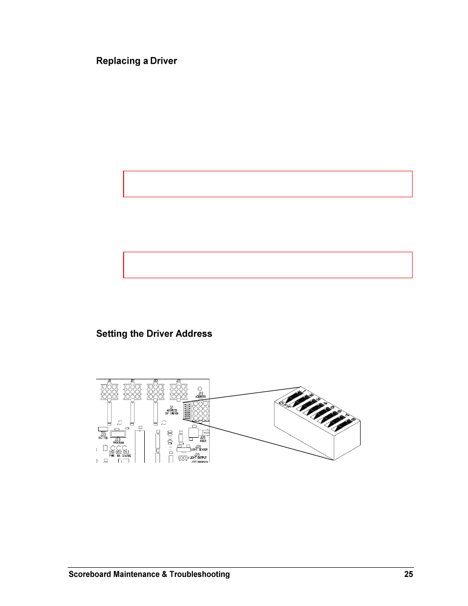
Since the same LED drivers can be used for many scoreboard models, each driver must be set
to receive the correct signal input, or address, for the model being used. Addresses are set
through the S1 dip switch on the driver (Figure 24) using a pen or small, pointed object.
Refer to the product specifications in Section 2 to determine the correct address setting of the
driver(s) in a particular scoreboard model and see Drawing A-290261 for addressing
information for driver addresses 1 – 128.
Another method of setting the driver address using the J19 address plug is available. This
address is set with jumper wires in a 12-pin plug which mates with a jack on the driver. Refer
to Drawing A-115078 for a listing of the wire/pin connections for driver addresses 1 – 128.
When using an address plug, it will not be possible to set the address with the S1 dip switch.
Figure 24: Driver Address Dip Switch
Note:
It may be helpful to label the cables to know which cable goes to which
connector when reattaching the driver.
Note:
The connectors are keyed and will attach in one way only. Do not attempt to
force the connections.