Fiber optic – Daktronics BA-2515-31 DistaView Outdoor LED Scoreboard User Manual
Page 22
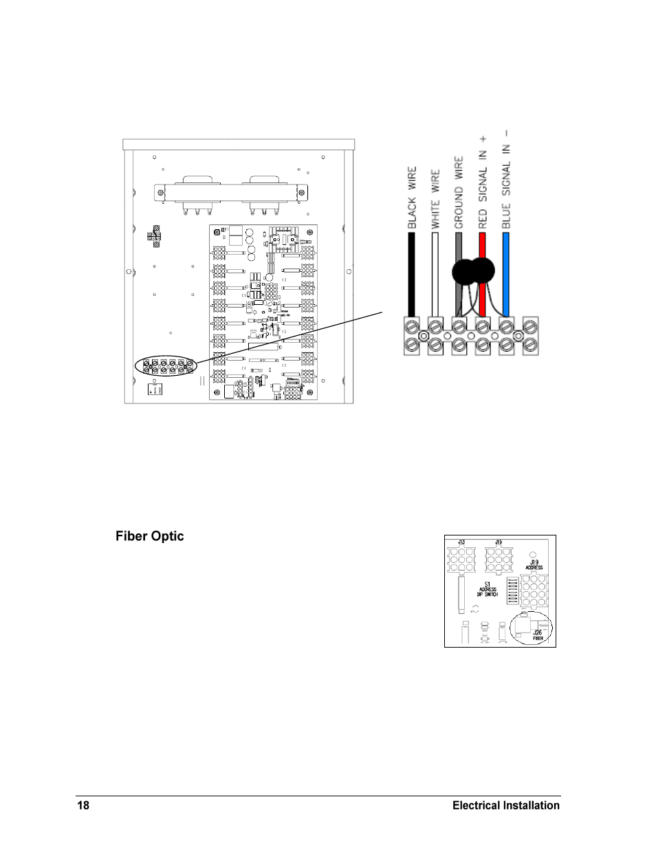
Connect the appropriate power and signal wires coming through the rear of the scoreboard to
the power terminal block (TB1), as shown in Figure 15. Refer to Drawings A-285469 and A-
285470 for a detailed layout of a 16- and 8-column driver enclosure, respectively.
TB1 has protection varistors across both “signal” terminals to the “ground” terminal. For
more information, refer to Drawings A-285892, A-286657, A-229706, and A-704861.
For signal cable, Daktronics recommends, as a minimum, single-pair, shielded cable, 22 AWG
(Daktronics part number W-1077). Two-pair shielded cable (W-1614) is preferred.
Another common signal communication method is fiber optic
cabling. A minimum cabling of multi-mode, 62.5/125 um, and 2-
core fiber cable is recommended (Daktronics part number is W-
1242). See Figure 17 for the location of the fiber connector on a 16-
or 8-column driver. This method requires a signal converter
between the All Sport console‟s scoreboard output and the fiber
optic cable (not provided by Daktronics).
Figure 15: Power/Signal
Terminal Block (TB1)
Figure 17: Driver Fiber
Connection Location
Figure 16: Driver Enclosure (16-column)