Termination – Daktronics BA-2515-31 DistaView Outdoor LED Scoreboard User Manual
Page 21
installation can verify ground resistance. Daktronics Sales and Service personnel can also
provide this service.
The display system must be earth-ground. The material for an earth-ground electrode differs
from region to region and may vary according to conditions present at the site. Consult local
and national electrical codes. The support structure of the display cannot be used as an earth-
ground electrode.
There are two types of power installation: installation with ground and neutral conductors
provided, and installation with only a neutral conductor provided. These two power
installations differ slightly, as described in the following paragraphs:
Installation with Ground and Neutral Conductors Provided
For this type of installation, the power circuit must contain an isolated earth-ground
conductor. In this circumstance, do not connect neutral to ground at the disconnect or at the
display as this would violate electrical codes and void the warranty.
Use a disconnect so that all ungrounded lines can be disconnected. The National Electrical
Code requires the use of a lockable power disconnect within sight of or at the display.
Installation with Only a Neutral Conductor Provided
Installations where no grounding conductor is provided must comply with Article 250-32 of
the National Electrical Code. If the installation in question meets all of the requirements of
Article 250-32, the following guidelines must be observed:
Connect the grounding electrode cable at the local disconnect, never at the display
driver/power enclosure.
Use a disconnect that opens all of the ungrounded phase conductors.
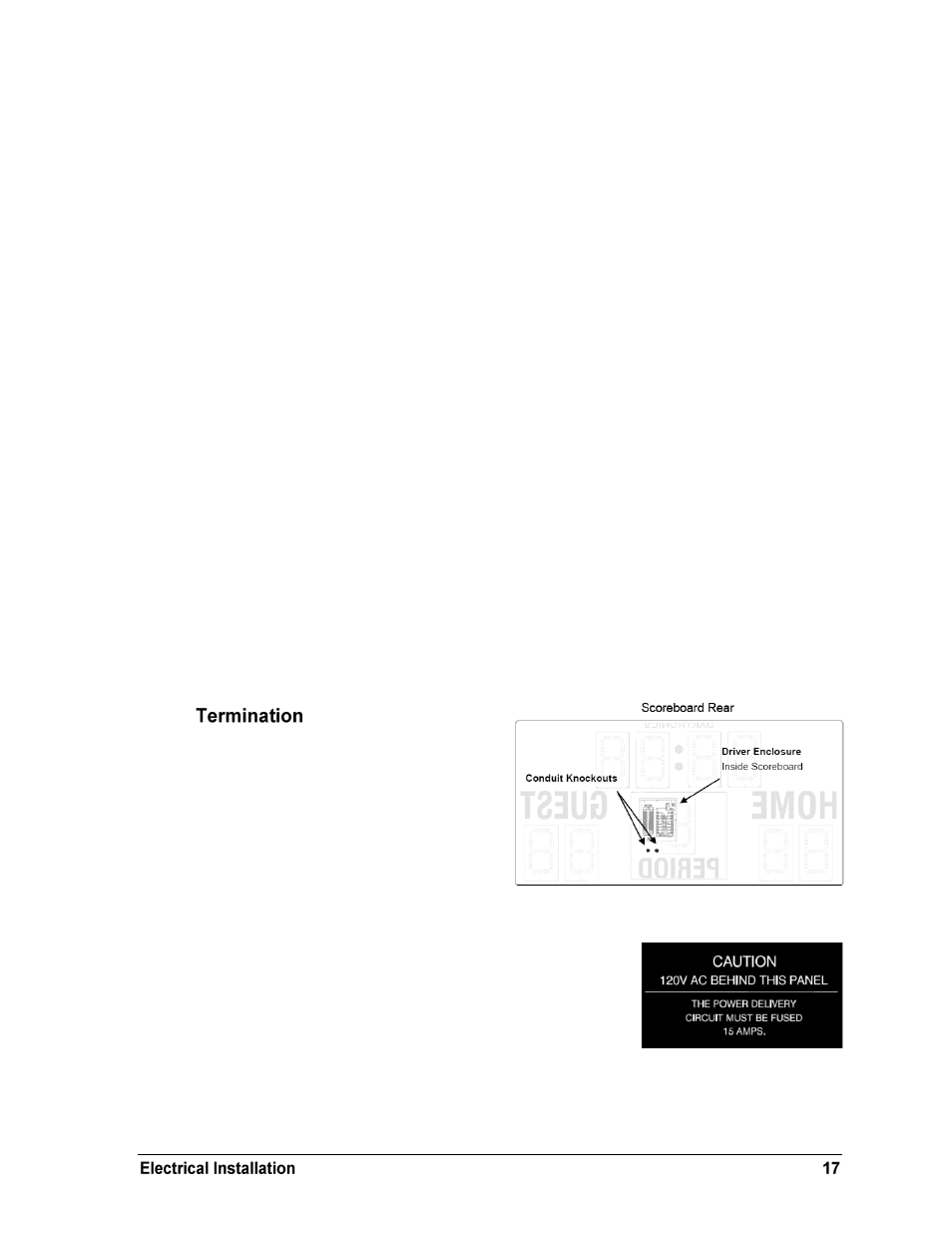
Power and signal cables are routed into the
scoreboard from the rear through two
conduit knockouts (Figure 13). All power
and signal wiring terminates at the driver
enclosure. Note that systems with radio
control do not require external signal
wiring.
Look for a warning label similar to Figure
14 to locate the front access panel to the
driver enclosure. Open the access door or digit panel and
remove the metal cover to expose the enclosure (Figure 16).
To gain access to the termination connector, open the access
door and remove the cover from the enclosure. Refer to the
component locations drawings for access locations.
Figure 13: Conduit Knockouts
Figure 14: Power Warning Label