Delta Electronics IPM- C Series User Manual
Page 8
.2.4 Output Voltage Set-Point Adjustment Range (Trim)
utput Voltage Set-Point Adjustment can be carried out by using an external resistor or
e set-point (please refer to
ments to Item 7.1-6,
ries
between the
TRIM pin and ground. For IPM12C0A0R04A, Please refer to the IPMR table for the desired
trim-up
can be calculated by the following equation and the datasheet can
8
O
external voltage source to increase or decrease the output voltag
e data sheet for the detailed specification). Refer all trim voltage require
th
7.1-7, 7.1.8, and refer all the design numbers to Evaluation Board Schematic.
(1) Output Voltage Set-Point Adjustment by using an external resistor
For IPM12C se
To implement Trim-up by using an external resistor, R
trim-up
must be connected
Vout. The value of R
also be referred for further information.
Ω
−
−
=
−
k
V
R
up
trim
261
.
0
9
.
0
752
.
3
out
To implement Trim-down by using an external resistor, R
trim-down
must be connected between
the TRIM pin and Vout. For IPM12C0A0R04A, Please refer to the IPMR table for the desired
out. The value of R
can be calculated by the following equation and the datasheet
V
trim-down
can also be referred for further information.
Ω
−
−
=
−
k
V
R
down
trim
621
.
5
9
.
0
072
.
1
out
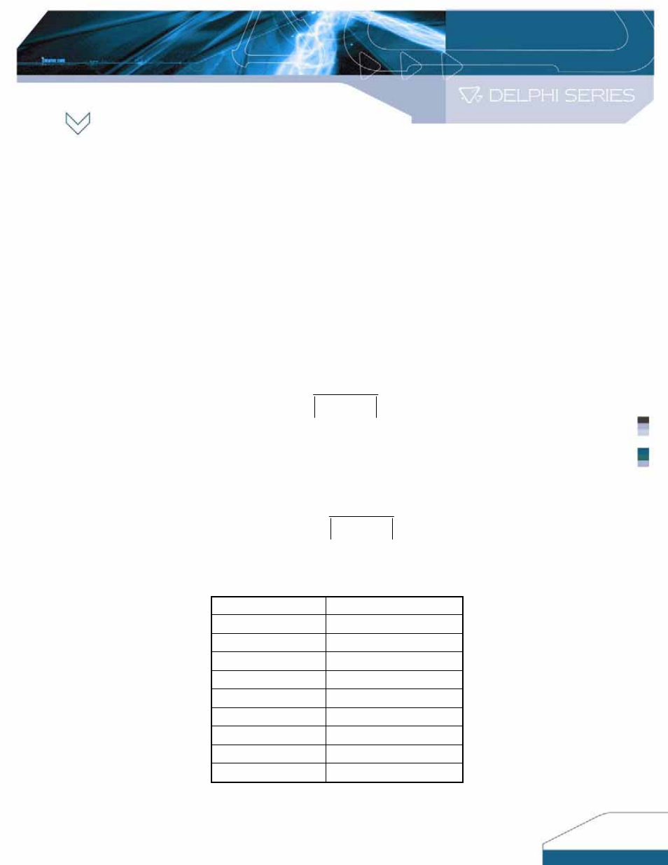
IPMR:
Rtrim values versus some commonly used Vout for IPM12C0A0R04A
.
Vout Rtrim
(Ω)
0.800 5.09K
0.900 Open
1.0 37.2K
1.2 12.2K
1.5 5.98K
1.8 3.90K
2.5 2.08K
3.3 1.30K
5.0 653
8