Delta Electronics IPM- C Series User Manual
Page 5
6)
ed for the trim-down or trim-up setting of the Output Voltage. For IPM, if the
converter requires a trim up, set SW3 to the Trim-up position. If the converter requires a
7)
l
resistors. For IPM12C0A0R04A, if the converter requires a trim-up to 5V, set the SW4_1
8)
rim-up, set the SW4_2 to
ON position and SW3 to trim-up position. If the converter requires a trim-down, set the
Subdivide switch NO.
For adjustable output
module
For constant output
module
trim down, set SW3 to the Trim-down position. For normal operating, turn off the SW3.
SW4 and SW5 are used for the Output Voltage Set-Point Adjustment by externa
to ON position and SW3 to trim-up position. If the converter requires a trim-down to 0.8V,
set the SW5_8 to ON position and SW3 to trim-down position.
For constant output voltage module, if the converter requires a t
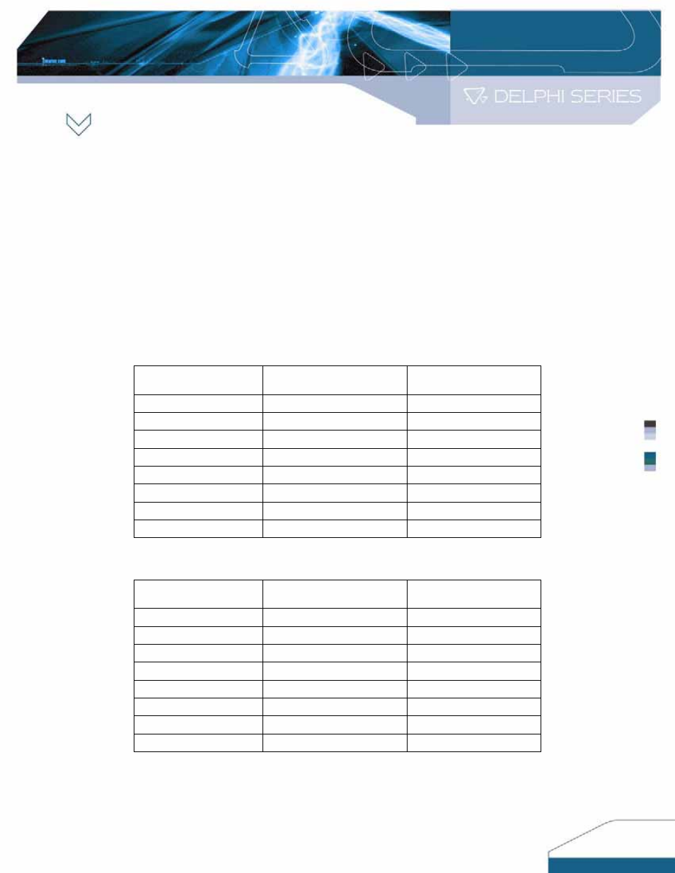
SW5_8 to ON position and SW3 to trim-down position. Please refer to the Function
Tables below for the setting details.
SW4 Function Table
SW4_1
5.0V setting
5.0V trim up
SW4_2
3.3V setting
3.3V trim up
SW4_3
2.5V setting
2.5V trim up
SW4_4
1.8V setting
1.8V trim up
SW4_5
1.5V setting
1.5V trim up
SW4_6
1.2V setting
1.2V trim up
SW4_7 1.0V
setting
1.0V trim up
SW4_8
0.95V setting
0.9V trim up
Note: Settings of SW4_1 and SW4_7 are for IPM12C se
Subdivide switch NO.
For adjustable output
module
For constant output
module
ries only
SW5 Function Table
SW5_1
-
5.0V trim down
SW5_2
-
3.3V trim down
SW5_3
-
2.5V trim down
SW5_4
-
1.8V trim down
SW5_5
-
1.5V trim down
SW5_6
-
1.2V trim down
SW5_7
-
1.0V trim down
SW5_8
0.80V setting
0.9V trim down
SW3 is us
5