Installation, Continued – Desa FDCFRN User Manual
Page 19
www.desatech.com
111244-01C
19
OPTIONAL WIRELESS HAND-HELD
REMOTE CONTROL ACCESSORIES
Remote-Ready Models Only
([C]GHRCB Series & [C]GHRCTB
Series)
Installing Receiver
1.
Disconnect wires from the control valve (see
Figure 26) .
2.
Locate the battery clip mounted on the back
of the receiver (see Figure 27).
3.
Slide 9-volt battery (not included) through the
clip.
4.
Attach the terminal wires to the battery (see
Figure 27).
5.
Connect wires from remote receiver to con-
trol valve as shown in Figure 28.
6.
Install remote receiver unit onto remote/
blower bracket using screws provided (see
Figure 28).
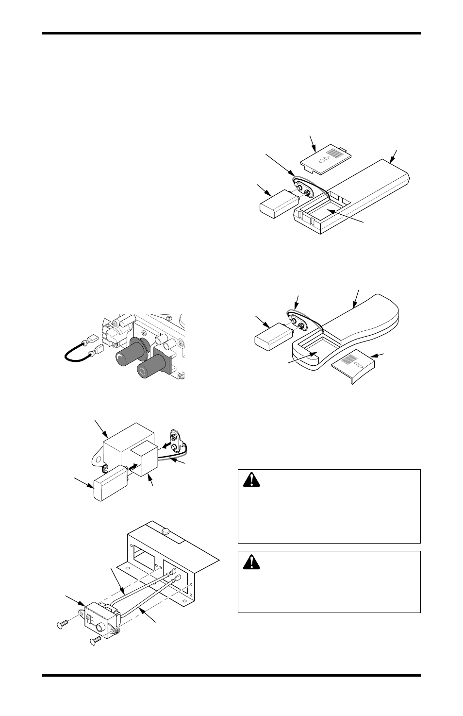
Installing 9-Volt Battery in Hand-Held
Remote Control Unit
1.
Remove battery cover on back of remote con-
trol unit.
2.
Attach terminal wires to the battery (not in-
cluded). Place battery into the battery housing.
3.
Replace battery cover onto remote control unit.
INSTALLATION
Continued
Figure 26 - Disconnecting Wires From
Control Valve
Figure 27 - Attaching Battery to Receiver
Battery Clip
9-Volt
Battery
Receiver
Terminal
Wires
O
F
F
P
ILO
T
O
N
H
I
L
O
Figure 28 - Installing Remote Receiver
Remote
Receiver
White Wire to
TH Terminal on
Control Valve
Red Wire to TPTH
Terminal on
Control Valve
Figure 29 - Installing Battery in Hand-
Held Remote Control Unit (GHRCB and
CGHRCB Series)
Battery Cover
9-Volt
Battery
Terminal
Wires
Remote
Control Unit
Battery
Housing
Figure 30 - Installing Battery in Hand-
Held Remote Control Unit (GHRCTB and
CGHRCTB Series)
Remote Control Unit
Battery
Cover
Terminal Wires
9-Volt
Battery
Battery
Housing
OPTIONAL WALL MOUNTED
THERMOSTAT - GWMT1
(Remote-Ready Models Only)
WARNING: Read and follow
installation instructions. Instal-
lation should be done by a quali-
fied installer familiar with low-
voltage wiring procedures.
WARNING: Do not connect
this thermostat to any electrical
source! Electrical shock and/or
fire hazard will occur.
1.
Remove jumper wire from control valve (see
Figure 26).