Modbus serial bus connections – Contemporary Control Systems BASremote Installation Guide User Manual
Page 8
TD040300-0II
8
Modbus Serial Bus Connections
The Modbus serial expansion port (MB) on the BAS Remote Master module
is non-isolated EIA-485 compatible. When connecting to other non-isolated
devices, care must be exercised to ensure that all non-isolated Modbus devices
share the same ground reference (COM) with the BAS Remote Master
module. This is usually accomplished by sharing the same power source.
Configure the Modbus baudrate and protocol using the BAS Remote Modbus
port web page.
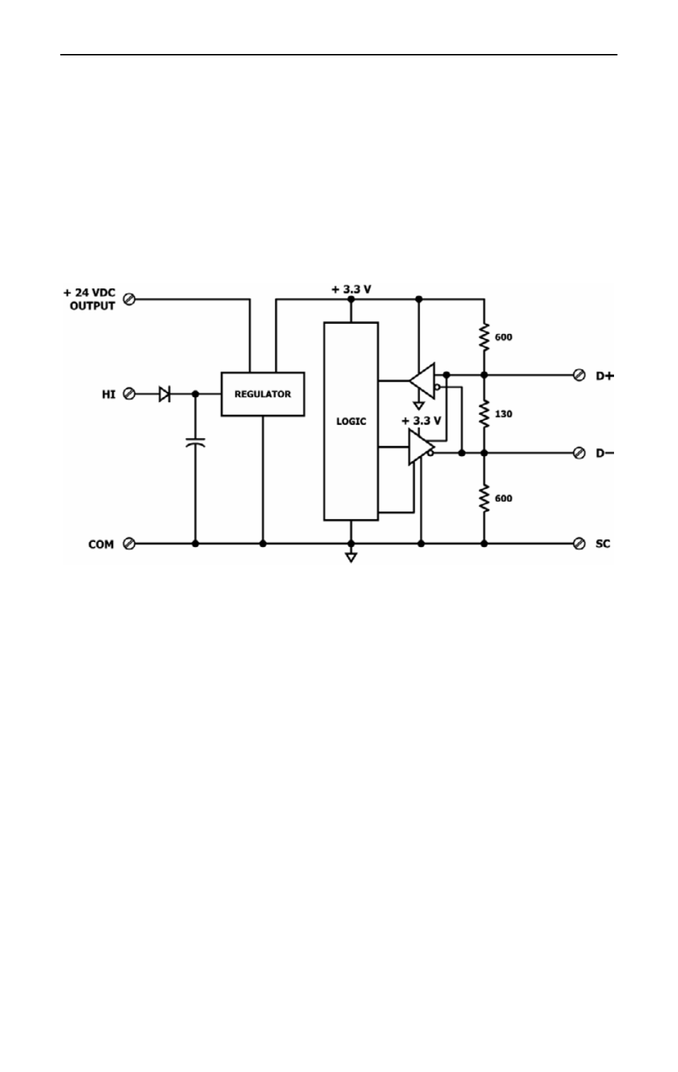
Figure 7 — Internal Termination and Bias
When connecting to an isolated 3-wire Modbus device, the signal common of
the isolated device must be connected to the SC pin between the MB and DN
ports. This ties the two reference points together for reliable communications.
Refer to Figure 9 for wiring details.
Modbus serial devices can only be attached to the MB port on the master
module. Refer to Figure 7 for details on the bias and termination network
present on the MB port. Together, these resistors approximate one 120 Ω
terminating resistor. Terminal D+ represents the more positive connection for
the EIA-485 Modbus serial network while D– represents the less positive
connection. Make corresponding connections to Modbus serial devices. The
last device on the bus should have applied bias and termination or just
termination. A shielded twisted-pair cable should be used with inter-
connecting devices. Connect the shields together and attached to chassis at
only one point. Refer to Figure 9 for wiring details.