Field connections – Contemporary Control Systems BASremote Installation Guide User Manual
Page 12
TD040300-0II
12
F
IELD
C
ONNECTIONS
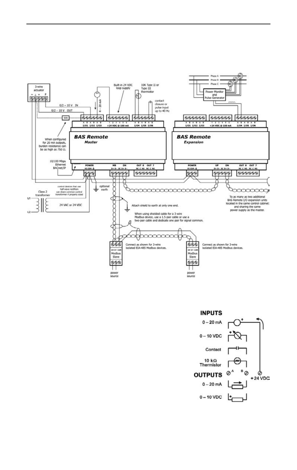
When attaching devices, observe proper cabling using Figure 9 as a guide.
Figure 9 — Sample Wiring Diagram
Wire Channels 1–6 so the most positive wire
goes to the ―A‖ terminal and the most negative
wire to the ―B‖ terminal.
The wiring options for Channels 1–6 are
shown in Figure 10. For each case in which
polarity matters, proper polarity is indicated.
Considerations in making field connections for
various types of input and output devices are
discussed in the following pages.
Figure 10 — I/O Options
(Channels 1–6)
See also other documents in the category Contemporary Control Systems Hardware:
- AI-FR Redundant Fibre Hubs (9 pages)
- AI Active Hubs (40 pages)
- AI-SRVR Servers to Ethernet Installation Guide (12 pages)
- AI-USB Adapters (12 pages)
- AI-SRVR Servers to Ethernet User Manual (20 pages)
- PCX20 Adapters (16 pages)
- MODHUB Active Hubs (32 pages)
- PCI20EX Adapters (12 pages)
- QuickLink Active Hubs (8 pages)
- USB222 Adapters (8 pages)
- BAScontrol20 Installation Guide (16 pages)
- BASgatewayLX (16 pages)
- BAScontrol20 User Manual (53 pages)
- BASremote Application Guide (13 pages)
- BASremote User Manual (firmware 2.x) (78 pages)
- BASrouter Installation Guide (Firmware 2.7.x) (24 pages)
- BASrouter Portable Installation Guide (Firmware 2.7.x) (20 pages)
- BASrouterLX Successful BASrouter Installation and Operation (3 pages)
- BASrouterLX Installation Guide (12 pages)
- BASrouterLX Application Guide (20 pages)
- CAN104 (8 pages)
- CANPCI (8 pages)
- BASview (81 pages)
- Compact Unmanaged Switches (4 pages)
- EIBA BAS Unmanaged Switches (4 pages)
- EIDX Managed Automation Switches Installation Guide for PoE Models (8 pages)
- EIPR Wired/Wireless VPN Router Installation Guide (4 pages)
- EIDX Managed Automation Switches Software Manual for Console Access (80 pages)
- EISK Managed Skorpion Switches Software Manual (83 pages)
- EIS UL864-Compliant Switches (8 pages)
- EISC Configurable Switches Installation Guide (8 pages)
- EISK Skorpion Switches EISK8-GT (4 pages)
- EISK Managed Skorpion Switches Installation Guide (4 pages)
- EIPR Wired/Wireless VPN Router Application Guide (14 pages)
- EISC Configurable Switches User Manual (36 pages)
- EISK Skorpion Switches EISK5-100T/FCS (4 pages)
- BACnet Cube I/O BMT-DI4 (3 pages)
- BACnet Cube I/O BMT-DI10 (3 pages)
- BACnet Cube I/O BMT-AI8 (4 pages)
- BACnet Cube I/O BMT-SI4 (3 pages)
- BACnet Cube I/O BMT-DO4 (3 pages)
- BACnet Cube I/O BMT-AO4 (3 pages)
- Sedona (27 pages)
- BACnet Cube I/O BMT-DIO4/2 (4 pages)