Interrupts, Indicator lights, Node id switch – Contemporary Control Systems PC10420 Adapters User Manual
Page 6: Field connections
TD874100-0IH
6
Interrupts
Interrupts can be invoked at jumper location
E1
which consists of a series of
rows of two posts each. Each row is labeled with an interrupt line
corresponding to one of the PC bus interrupt designators. To enable an
interrupt, insert a jumper across a pair of posts corresponding to the desired
interrupt. Only one interrupt can be selected; therefore, only one jumper is
supplied. If no interrupts are desired, remove all jumpers at E1. The default
interrupt setting is INT 2.
Indicator Lights
There is a dual LED located at the PC10420 front plane. The yellow LED
indicates that the PC10420 is being accessed via its I/O address. The green
LED indicates that the PC10420 is receiving ARCNET traffic from the
network.
Node ID Switch
Although not always necessary with the COM20020, the PC10420 provides
a separate input port that reads an 8-bit DIP switch (SW1) located near the
board edge. This switch is intended to serve as a node ID switch, although it
can serve as a general purpose switch if desired. The node ID switch has no
connection to the COM20020 ARCNET controller chip.
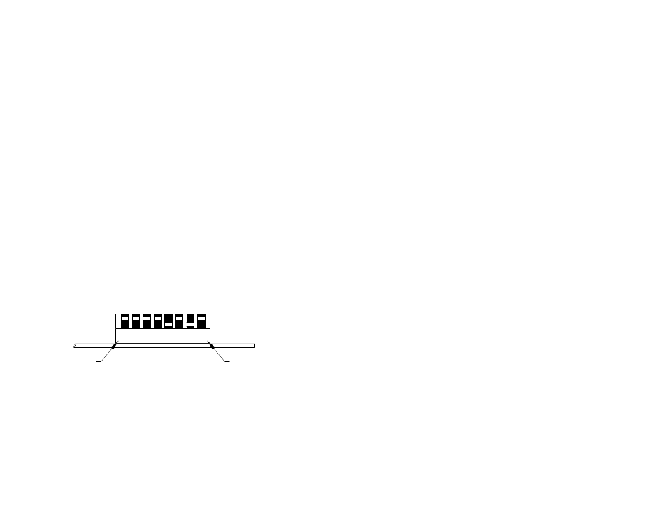
The most significant bit (MSB) is switch position 1, and the least significant
bit (LSB) is switch position 8. A switch in the open position (off position or
away from the printed circuit board) introduces a logic “1.” Figure 1 shows
the node ID switch. In this example, the switch is set to hexadecimal
address F5.
Figure 1—Node ID Switch
FIELD CONNECTIONS
The PC10420 is available in several transceiver options. Each transceiver,
which is matched to a particular cable type, is identified by a three-character
suffix appended to the model numbers. The capabilities of each transceiver
differs.
MSB
LSB