Bias – Contemporary Control Systems PC10420 Adapters User Manual
Page 11
TD874100-0IH
11
Incorporating a resistance value less than 120 ohms is not recommended
since it may excessively load the EIA-485 transceivers.
Bias
In addition to the termination, it is also necessary to apply bias to the
twisted-pair network so that when the line is floated, differential receivers
will not assume an invalid logic state. There are two precision bias resistors
(Rb) of equal value on each daughter board. One resistor is tied to the +5 V
line while the other is tied to ground. Each resistor has a jumper associated
with it. If the two jumpers are installed, the resistor tied to +5 V is
connected to the (+) signal line while the grounded resistor is connected to
the (–) line. This voltage drop will bias the differential receivers into the
“1” state when no differential drivers are
enabled. Differential receivers typically switch at
or near zero volts differential and are guaranteed
to switch at +/–200 mV. Through the transition
point, 70 mV of hysteresis will be experienced.
Therefore, a positive bias of 200 mV or greater
will ensure a defined state. We recommend that
bias be applied to both ends of the wiring
segment by installing the two end jumpers
located at position
E1
on the daughter board.
This is to be done for only the two NIMs
located at the end of the segment. All other
NIMs will have their jumpers removed.
The termination and bias rules are simple. If the NIM is located at the
extreme ends of the segment, install all three jumpers at location E1 on the
daughterboard. If the NIM is located between the two end NIMs, remove all
three jumpers. If external termination is desired, remove the middle jumper
at E1.
For EIA-485 DC operation, it is very important that all devices on the
wiring segment be referenced to the same ground potential in order that the
common mode voltage requirement (+/–7 Vdc) of the EIA-485 specification
is achieved. This can be accomplished by running a separate ground wire
between all PC computers or by relying upon the third wire ground of the
power connector assuming that the DC power return is connected to chassis
ground on the PC computer. Another approach would be to connect the DC
common of each PC computer to a cold water pipe. Connected systems, each
with different elevated grounds, can cause unreliable communications or
damage to the EIA-485 differential drivers. Therefore, it is important that an
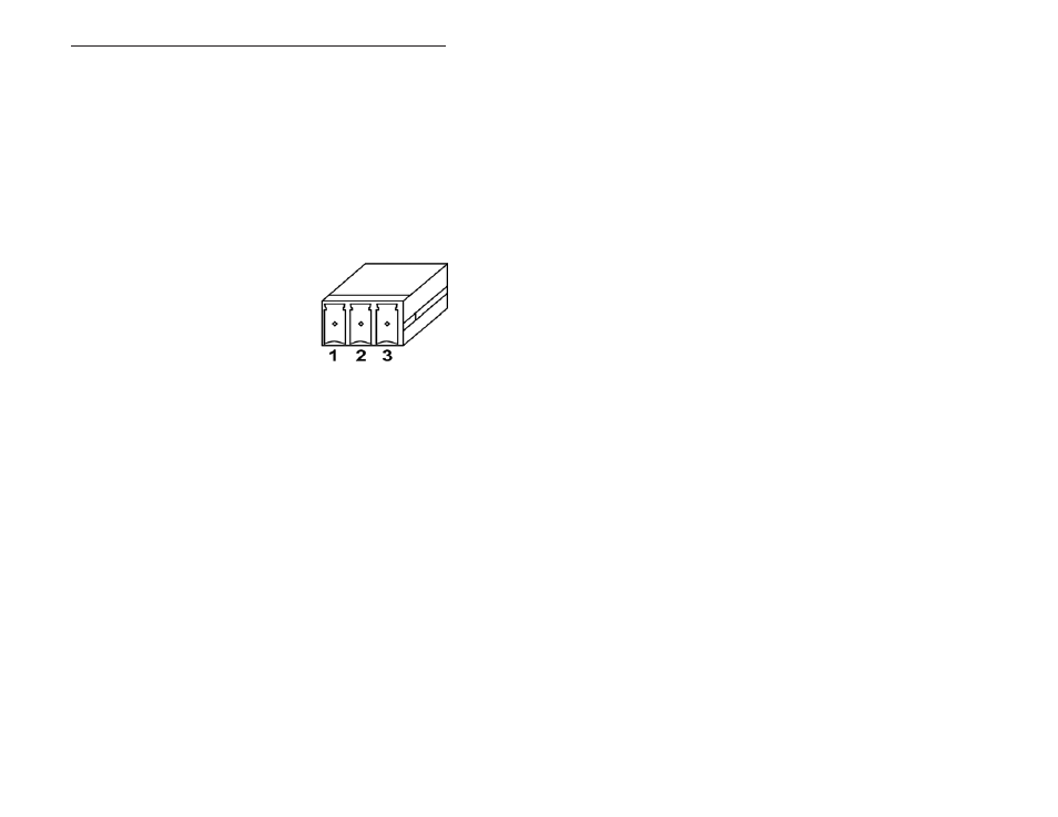
adequate grounding method be implemented. A ground connection can be
found at pin 3 of the screw terminal connector.
Figure 7—Screw
Terminal Connector
Numbering Orientation