Electromagnetic compatibility – Contemporary Control Systems PC10420 Adapters User Manual
Page 13
The cabling rules of the -485X are similar to the -485D. Dual RJ-11
connectors and one three-position screw terminal connector are used in each
NIM. Wire a maximum of 13 NIMs in a daisy-chain fashion leaving the end
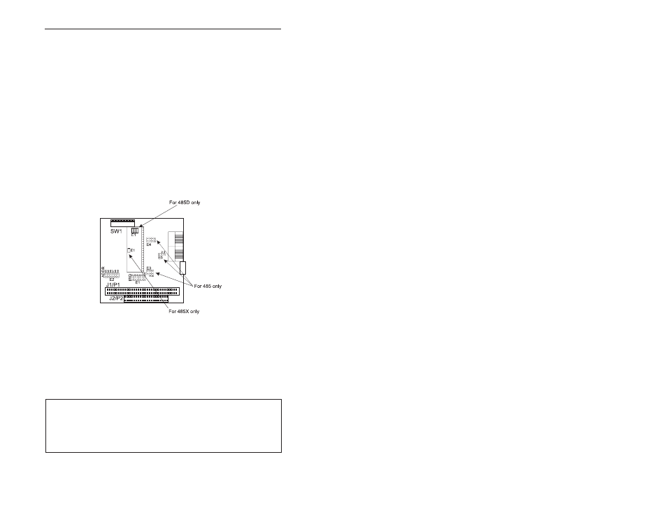
NIMs with vacant RJ-11 connections. On these NIMs insert a jumper at E1
on both -485X daughter boards to invoke 120-ohm termination resistors or
leave the jumpers open and insert RJ-11 style passive terminators in each of
the two vacant RJ-11 jacks. Termination can also be accomplished by
installing a 120-ohm, ¼ watt resistor across pins 1 and 2 of the screw
terminals at each end of the bus segment. Refer to Table
s 4 and 5 for
connector pin assignments. Termination should not be applied to any of the
NIMs located between the two end NIMs of the segment. Do not mix -485D
and -485X NIMs together on one segment; however, bridging of the
technologies is possible using active hubs with the appropriate transceivers.
To extend -485X segments, use a hub as discussed under the -485D section.
Make sure that the active hub transceivers are of the -485X type. Cable
inversion is not of any consequence.
Figure 8—Jumper settings for EIA-485 models.
Electromagnetic Compatibility
The PC10420 series complies with Class A radiated and conducted
emissions as defined by FCC Part 15 and EN55022. This equipment is
intended for use in non-residential areas.
TD874100-0IH
13
Warning
This is a Class A product as defined in EN55022. In a domestic
environment this product may cause radio interference in which case
the user may be required to take adequate measures.