Termination – Contemporary Control Systems PC10420 Adapters User Manual
Page 10
TD874100-0IH
10
do not set the COM20020 to backplane mode for EIA-
485 communication as recommended in SMSC’s
application note and data sheet since Contemporary
Controls (CC) implements the same signaling on this
daughter board. With our approach, the same software
driver used for coaxial networks will function
with the EIA-485 version of the PC10420 without
modification.
One three-position screw terminal (see
Figure 7)
and two RJ-11 connectors are
supplied on each NIM and are bussed together
to provide a convenient daisy-chain method for
connecting multiple nodes onto one segment.
This segment can be up to 900 feet long of
Category 5 unshielded twisted-pair cable, and
as many as 17 nodes can occupy the segment.
Make sure that the phase integrity of the wiring
remains intact. Pin 3 of the modular jack on
each NIM must be connected together. The same
applies to pin 4. Most modular (satin cable)
telephone wiring inverts the phase of the wiring,
thereby reversing the connections to pins 3 and 4
at each end. Do not use this type of cable. Some
modular cable is not even twisted. Be sure to use the proper cable. Refer to
Tables 4 and 5 for connector pin assignments.
Termination
Each end of the segment must be terminated in the characteristic impedance
of the cable. A 120-ohm resistor can be invoked with a jumper which resides
on the EIA-485 daughter board. With the middle jumper inserted at location
E1
on the daughter board, 120 ohms of resistance is applied across the
twisted-pair. With the jumper removed, no termination is applied. If it is
desired to apply external termination instead, remove this jumper and insert
an RJ-11 style terminator in the unused RJ-11 modular jack or install a 120
ohm, 1/4 watt resistor across pins 1 and 2 on the screw terminal connector.
Table 4—Modular
Connector Pin
Assignments for -TPB
Table 5—Screw Terminal Connector
Pin Assignments for -485, -485D -485X and -TPB
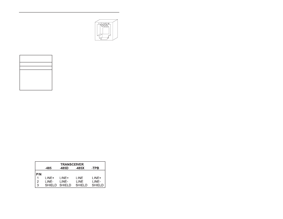
Modular Connector Pin
Assignments
6-Contacts
Pin
Usage
1
Not Available
2
Not Used
3
Line+
4
Line
5
Not Used
6
Not Available
–
Figure 6—Modular Jack
Numbering Orientation