Comtech EF Data EQ90 Series User Manual
Page 38
Operation
EQ90 Amplitude Equalizer
3-14
Rev. 2
The parabolic bandwidth of the equalizer can be increased in one of two ways.
•
The first involves using two equalizers, each with half the required peak delay,
and tuning them both to the same center frequency. This increases the parabolic
bandwidth by a factor of two.
•
The second method requires two equalizers of the same delay but stagger-tuned
about the center frequency of the filter. This method can increase the parabolic
bandwidth between two and four times depending upon the delay ripple
requirements.
The second method of equalization requires fewer sections to achieve an equalized
response, and in addition, permits adjustment for non-symmetrical filter delay responses.
As additional delay equalizers are added to the system, their frequencies will be set
further and further away from the transponder center frequency.
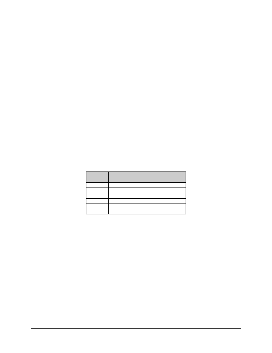
Equalizer parameters for the satellite equalizer, which will provide a nearly ideal
parabolic group delay response over a 36 MHz bandwidth with a peak-to-peak (P-P)
delay magnitude of 40 ns are as shown in Figure Chapter 3-4.
Table Chapter 3-4. Peak-to-Peak Delay Magnitude
Section
Number
Center Frequency
(MHz)
P-P Delay Over
36 MHz (ns)
1 56.5
14
2 67.8
14
3 77.5
14
4 62.5
14
5 72.0
14
6 83.5
14
Note: The adjacent equalizer sections are frequency staggered to minimize interactions.
The peak-to-peak delay is measured about the center frequency of the equalizer delay
peak after its amplitude response was for maximum flatness, over the 52 to 88 MHz IF
bandwidth. The above parameters will produce an equalizer group delay characteristic as
shown in Figure Chapter 3-12.