Instructions for the installer – Campomatic C964XRSIFSCN User Manual
Page 33
33
�
�
�
�
�
�
�
�
�
� �
� �
� �
�
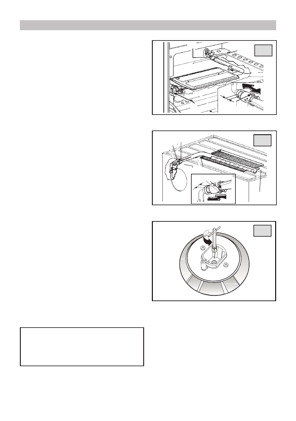
28
29
30
OVEN BURNER (fig. 28)
The burner is installed on the oven base and is covered
by the bottom plate which must always remain in that
position during oven operation,
To adjust the primary air, light the burner and,
watching the flame, slacken screw (A) and adjust
sleeve (B) to obtain the X openings indicated in the
table on page 26. Lock screw (A) in place once the
adjustments have been made.
GRILL BURNER (fig. 29)
To adjust the primary air, light the burner and,
watching the flame, slacken screw (A) and adjust
sleeve (B) to obtain the X openings indicated in the
chart on page 26. Lock screw (A) in place once the
adjustments have been made.
CONVERSIONS
REPLACING THE INJECTORS
Our burners can be adapted to different types of gas by
simply installing the injectors suitable for the gas you
want to use. To help the installer, the table on page 26
gives the burner nominal heat input, injector diameter
and operating pressure of the different gas types.
Comply with the following instructions:
Injector replacement - Hob burners.
To change the injectors on the hob, remove the burner
cup and head and with a 7 mm Ø socket spanner
replace them (fig. 30).
Injector replacement - Oven burner.
Remove oven base. Remove screw (D) which will
release burner and give access to the injector (C)
(fig. 28). Unscrew injector and replace it. Replace
burner and replace screw (D).
Injector replacement - Grill burner.
Remove screw (D) which will release burner and give
access to the injector (fig. 29).Unscrew injector (C)
and replace it. Replace burner and replace screw (D).
After having replaced the injectors, it will be
necessary to proceed with burner adjustment
as explained in the previous paragraphs. The
technician must replace any seals after the
adjustments have been made.
INSTRUCTIONS FOR THE INSTALLER