Status byte (in process data mode) – BECKHOFF KL3681 User Manual
Page 29
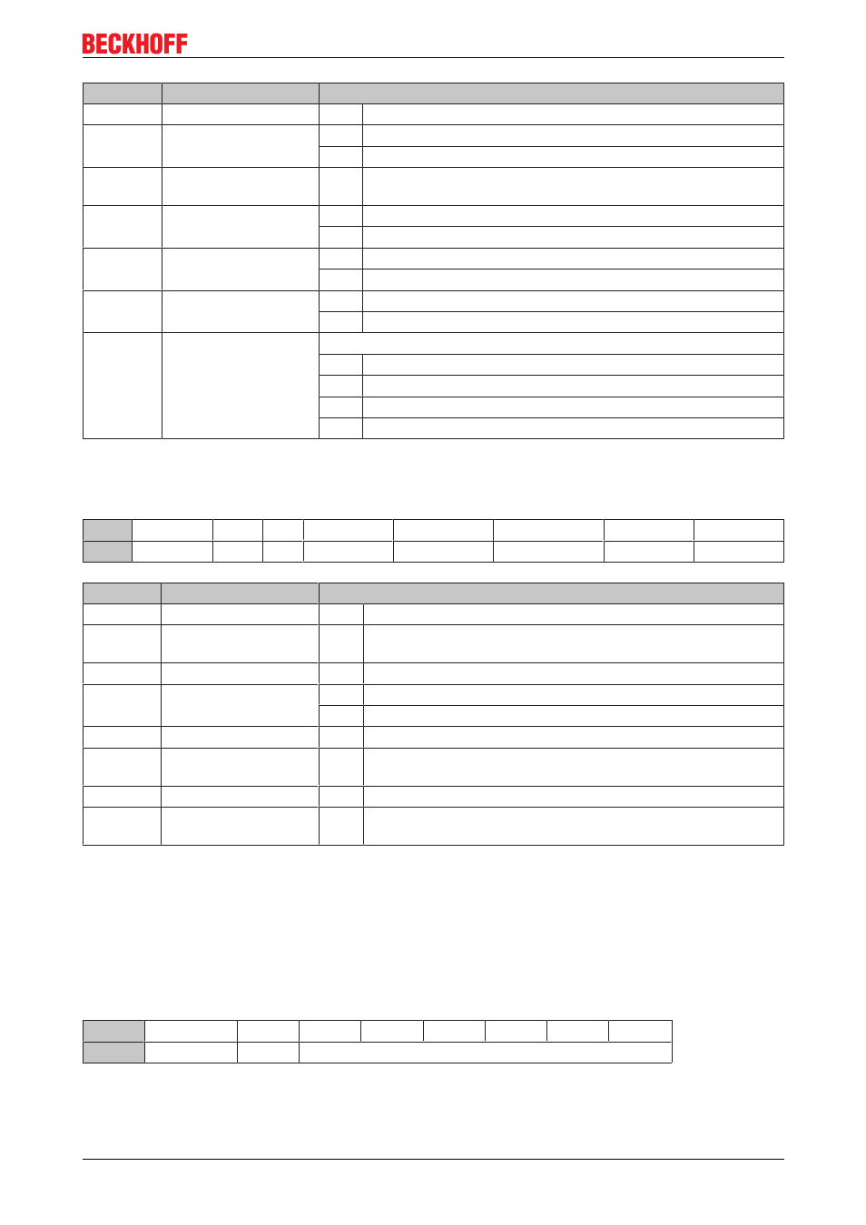
Access from the user programm
Bit
Name
Description
CB.7
RegAccess
0
bin
Register communication off (process data mode)
CB.6
R/W
0
bin
Read access
1
bin
Write access
CB.5
StartCalibration
1
bin
initiates an automatic correction of the internal measuring range
(only if register R33 = 4)
CB.4
disAutorange
0
bin
auto range enabled
1
bin
auto range disabled
CB.3
Voltage/Current
0
bin
Voltage
1
bin
Current
CB.2
DC/AC
0
bin
DC
1
bin
AC
CB.1, CB.0 Range
Measuring range (see also CB.2)
00
bin
3 V or 1 A
01
bin
30 V or 10 A
10
bin
300 V
11
bin
300 mV or 100 mA
Status byte (in process data mode)
The status byte (SB) is located in the input image [
28] and is transmitted from terminal to the controller.
Bit
SB.7
SB.6
SB.5 SB.4
SB.3
SB.2
SB.1
SB.0
Name RegAccess Error
noAutorange data Invalid
extended range overrange
underrange
Bit
Name
Description
SB.7
RegAccess
0
bin
Acknowledge for process data mode
SB.6
Error
1
bin
measuring range exceeded, over or under range, the error LED
shines or converting error or invalid measuring range
SB.5
reserved
0
bin
reserved
SB.4
0
bin
auto range is enabled
1
bin
auto range is disabled
SB.3
data invalid
1
bin
invalidprocess data, e.g. invalid value, e.g. filter latency, start up
SB.2
extended range*
1
bin
The extended measuring range (~10% of upper range value) is
used (hysteresis area of auto range functionality).
SB.1
overrange
1
bin
Exceeding of the electrical measuring range
SB.0
underrange
1
bin
Undershooting of the electrical measuring range at DC mode
(not displayed in AC mode
*) The extended range is only available for the measuring ranges 300 mV, 3 V, 30 V and 100 mA.
Register communication
Control byte (at register communication)
The control byte (CB) is located in the output image [
28] and is transmitted from the controller to the
terminal.
Bit
CB.7
CB.6
CB.5
CB.4
CB.3
CB.2
CB.1
CB.0
Name
RegAccess
R/W
Register no.
KL3681, KS3681
29
Version 2.0.0