5 access from the user programm, 1 process image, 2 control and status byte – BECKHOFF KL3681 User Manual
Page 28: 5access from the user programm
Access from the user programm
5
Access from the user programm
5.1
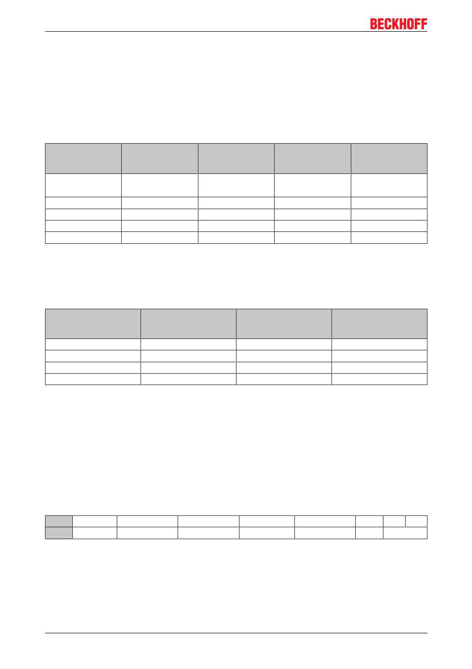
Process image
Complex mapping
The following 9 bytes are transferred bidirectionally between KL3681 and control:
Byte offset (with
out word align
ment*)
Byte offset (with
word alignment*)
Format
Input data
Output data
0
0
Byte
Status byte (SB
[
Control byte (CB
[
28])
1
2
Word
DataIN0
DataOUT0
3
4
Word
DataIN1
DataOUT1
5
6
Word
DataIN2
DataOUT2
7
8
Word
DataIN3
DataOUT3
*) Word alignment: The Bus Coupler places values on even byte addresses
Compact mapping (from firmware version 1C)
The following 8 bytes are transferred bidirectionally between KL3681 and control:
Byte offset (with and
without word align
ment*)
Format
Input data
Output data
0
Word
DataIN0
DataOUT0
2
Word
DataIN1
DataOUT1
4
Word
DataIN2
DataOUT2
6
Word
DataIN3
DataOUT3
*) word alignment has no effect with compact mapping
5.2
Control and status byte
Process data mode
Control byte (in process data mode)
The control byte (CB) is located in the output image [
28] and is transmitted from the controller to the
terminal.
Bit
CB.7
CB.6
CB.5
CB.4
CB.3
CB.2
CB.1 CB.0
Name RegAccess StartCalibration StartCalibration disAutorange
Voltage/Current DC/AC Range
KL3681, KS3681
28
Version 2.0.0