Electrical characteristics curves – Delta Electronics S36SS User Manual
Page 4
4
ELECTRICAL CHARACTERISTICS CURVES
Figure5
:
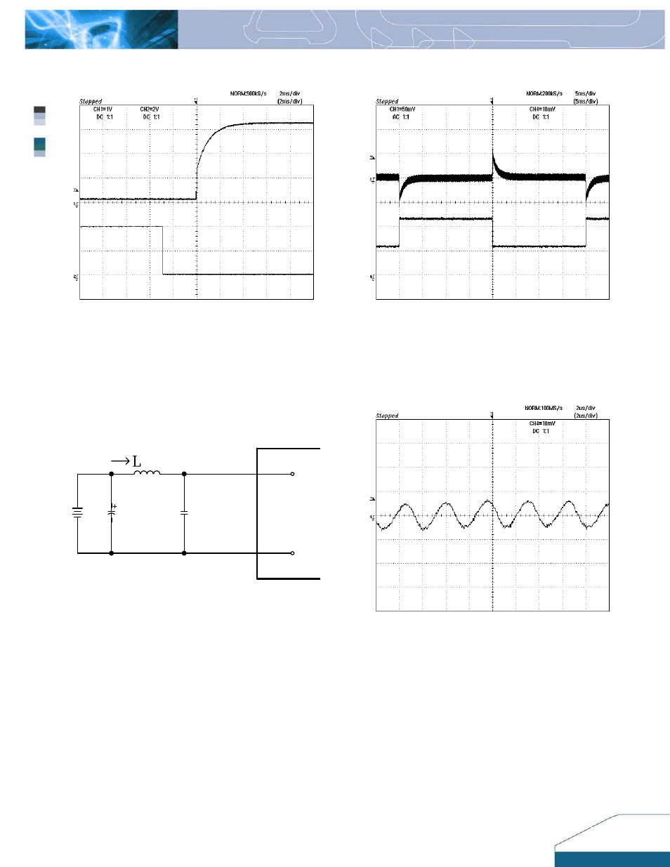
Turn-on transient at zero load current (2 ms/div). Top
Trace: Vout (1V/div); Bottom Trace: ON/OFF Control (2V/div).
Figure
6:
Output voltage response to step-change in load
current (50%-100%-50% of Io, max; di/dt = 0.1A/µs). Load
cap: 10µF, 100 m
ΩESR tantalum capacitor and 1µF
ceramic capacitor. Top Trace: Vout (50mV/div), Bottom
Trace: Iout (2A/div).
20
﹫
100KHz
℃
20
℃
100KHz
﹫
Ω
ESR< 0.3
ESR< 0.3
TEST
12uH
Cs:68uF/100V
68uF/100V
s
i
Vi(-)
Vi(+)
Ω
Figure 7
:
Test set-up diagram showing measurement points for
Input Reflected Ripple Current (Figure 8).
Note: Measured input reflected-ripple current with a simulated
source Inductance (L
TEST
) of 12 µH. Capacitor Cs offset possible
battery impedance.
Figure 8:
.
Input Reflected Ripple Current, is, at full rated
output current and nominal input voltage with 12
µ
H source
impedance and 68
µ
F electrolytic capacitor (2 mA/div).
- AC Motor Drive VFD-G (183 pages)
- SMT Power Inductor SIL104R (1 page)
- Q48SB (2 pages)
- Planar DC/DC Transformer ER/ER(Plate) 22 (1 page)
- SMT Power Inductor HCB1190B (1 page)
- Series E48SR (15 pages)
- E48SR12007 (15 pages)
- SMT Power Inductor SIWC1360 (1 page)
- PFC Chokes PFC2815V Series (1 page)
- SMT Power Inductor SIB86 (1 page)
- PMC-24V050W1AA (2 pages)
- SMT Power Inductor HCB1050 (1 page)
- SMT Power Inductor HAH1330 (1 page)
- PFC Chokes PFC4120V Series (1 page)
- PFC Choke PFC3520V Series (1 page)
- SMT Power Inductor HCB1047B (1 page)
- SMT Power Inductor HAH1365 (1 page)
- SMT Power Inductor HMS1355 (1 page)
- Series S48SA (13 pages)
- E48SC (2 pages)
- SMT Power Inductor SILM106 (1 page)
- Delphi Series L48DB (2 pages)
- S48SA (13 pages)
- E36SR (2 pages)
- 3KVA (31 pages)
- SMT Power Inductor HMU1056L (1 page)
- Through Hole Power Inductors THCBR1090 (1 page)
- SMT Power Inductor SIL625 (1 page)
- SMT Power Inductor 1378(S) (1 page)
- Through Hole Power Inductors 1411 (1 page)
- Current Sense Transformers TCE1310H (1 page)
- H48SR (13 pages)
- Series E48SH (15 pages)
- AC Motor Drive VFD-EL (209 pages)
- Through Hole Power Inductors THAH1095 (1 page)
- Suppression Inductors LFU09V (1 page)
- SMT Power Inductor HCB0740A (1 page)
- Power Output Module DVPPS01 (2 pages)
- SMT Power Inductor SIR74 (1 page)
- L36SA (2 pages)
- 4.5V~ 5.5V (3 pages)
- Delphi Series V48SB (2 pages)
- Series S48SP (14 pages)
- Series 240W (11 pages)
- Delphi Series E24SR (15 pages)