Installing optional controls – Desa (V) CB36(N User Manual
Page 11
10
www.desatech.com
117437-01
INSTALLING OPTIONAL CONTROLS
Installing Optional Wall Mount Switch - GWMS2
Installing Optional Wireless Hand-Held Remote Control - HRC100 Series
INSTALLING OPTIONAL WALL MOUNT
SWITCH - GWMS2
INSTALLING OPTIONAL CONTROLS
1. Connect one terminal of 15 ft. wire from the wall switch to the
male connector on the high limit harness. Connect remaining
wire terminal to the TH terminal on the valve. Make sure that
the wire terminals are in the positions on the unit as pictured
in
Figure 16. If wires are not connected as shown the switch
will not work.
2. Route the 15 ft. wire through hole openings with bushings
provided on either side of the fi replace cabinet.
3. Connect one bare wire end to each of the terminals of the
GWMS2 wall switch.
4. Install the wall switch and cover in the wall.
IMPORTANT: Do not use any other wire than that provided with
the GWMS2 wall switch kit. Do not exceed 15 ft. of distance from the
valve connection. Using wire of higher gage or turns or exceeding
the minimum distance will increase resistance at the control valve
causing unreliable performance of the fi replace controls.
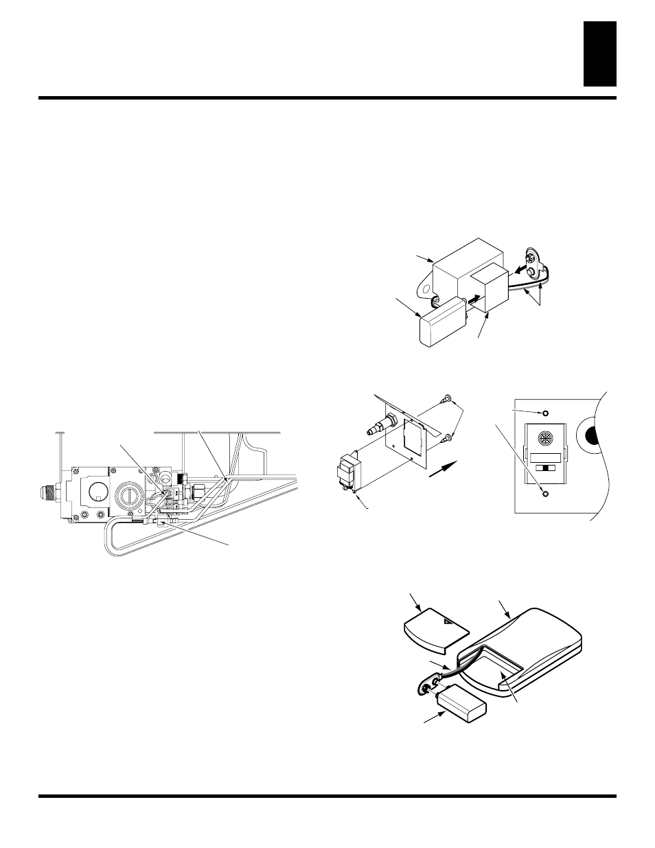
Figure 16 - Connecting Remote Receiver or Wall Switch to
the Gas Control Valve
INSTALLING OPTIONAL WIRELESS HAND-
HELD REMOTE CONTROL - MODEL HRC100
Installing Remote Receiver
1. Open bottom louver and locate the switch bracket on the right
2. Locate the battery clip mounted on the back of the receiver.
Slide a 9-volt alkaline battery (not included) through the clip
3. Attach the terminal wires to the battery. (see Figure 17).
4. Connect one wire from receiver to the male connector on high
limit harness and one to “TH” on control valve (see Figure 16).
5. Locate the two plastic mounting clips provided with the kit.
6. Use the clips to mount the receiver on remote mounting bracket.
as shown in Figure 18.
RECEIVER
REMOTE
TOWARDS FRONT
PLASTIC
CLIPS
MOUNTING
REMOTE ON OFF
Figure 18 - Mounting Remote Receiver to Bracket
Figure 19 - Installing Battery in Hand-Held Control Unit
(HRC100 Series)
Installing 9-Volt Alkaline Battery in Hand-Held Remote
Control Unit
1. Remove battery cover on back of remote control unit.
2.
Attach terminal wires to a 9-volt alkaline battery (not included).
Place battery into the battery housing. (see Figure 19).
3. Replace battery cover onto remote control unit..
9-Volt Alkaline
Battery
Receiver
Terminal Wires
Battery Clip
Figure 17 - Attaching Alkaline Battery to Receiver
Battery Cover
Remote
Control Unit
Battery
Housing
9-Volt
Battery
Terminal
Wires
Remote Receiver
or Wall Switch
to Terminal
Marked "TH"
Male Connector to
Remote Receiver
or Wall Switch
Wire Harness
From High
Limit Switch