Example 3: generator overload, Example 4: intertie, Example 3: generator overload -3 – Basler Electric BE1-32R User Manual
Page 13: Example 4: intertie -3, Figure 1-3. power relay start/stop control -3, Figure 1-4. power relay distribution protection -3
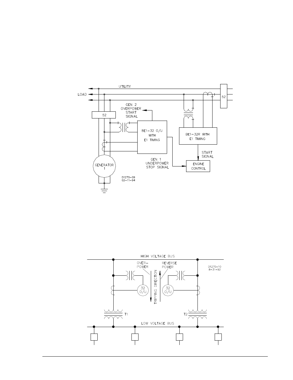
In the second configuration, the start signal is generated in the same manner as that of Figure 1-2. The
start signal setpoint may be set above the import power setting. The stop signal will require an
underpower relay on the generator output. This system is illustrated in Figure 1-3.
Example 3: Generator Overload
When excessive load has been connected to a generating system, the directional power relay can initiate
corrective action. Corrective action could be energizing an alarm to alert the station operator. For
automated systems, corrective action could be initiating the sequence to either shed non-critical load or to
start and parallel an in-house generator to assume the excess load.
Figure 1-3. Power Relay Start/Stop Control
Example 4: Intertie
Another typical use of the directional power relay, addresses excessive load and concerns distribution
protection (Figure 1-4). A high voltage bus supplies two transformers: T1 and T2. Both T1 and T2 can
supply all connected load. However, neither T1 nor T2 alone can supply the total load. A BE1-32O/U,
over/underpower directional relay can protect this distribution system by providing overload protection for
each transformer (overpower function) or by sensing power flow through the transformers (reverse power
function) in an undesired direction.
Figure 1-4. Power Relay Distribution Protection
9171100990 Rev R
BE1-32R, BE1-32O/U General Information
1-3