Example 2: co-generator control, Example 2: co-generator control -2, Figure 1-2. power relay start control -2 – Basler Electric BE1-32R User Manual
Page 12: Table 1-1. motoring reverse power requirements -2
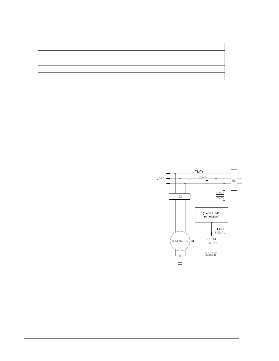
Table 1-1 represents the reverse power requirements to motor a generator when the prime mover is
rotating at synchronous speed with no input power supplied by the prime mover.
Table 1-1. Motoring Reverse Power Requirements
Prime Mover Type
Percent of Rated kW
Hydro Turbine
0.2 to 2.0
Steam Turbine (condensing or non-condensing)
0.5 to 3.0
Diesel Engine (no cylinders firing)
Up to 25
Gas Turbine
Up to 50 (due to compressor load)
The Reverse Power Relay is generally set for levels as low as possible with steam turbines typically being
set not higher than three percent and diesels and gas turbines slightly below ten percent.
Time delays are usually employed to avoid nuisance tripping caused by reverse power transient surges
that may result from synchronizing or other system disturbances. These time delays are typically set from
2 to 10 seconds, but may be set as high as 30 seconds or more.
An operating condition with very low power levels at a low power factor may not be detected by this
product. For very low power levels at power factors of 0.10 or lower, contact Basler Electric for
recommended products.
Example 2: Co-Generator Control
In this example, cogeneration concepts are addressed.
To illustrate, assume that the cogeneration system has
automatic engine controls, an auto-synchronizer,
automatic kW, and kvar controls. The system operates
virtually by itself. The only function lacking is the
start/stop signals to the generators. Two system
configurations may be implemented to generate contact
closures for start/stop signals.
The first configuration (Figure 1-2) shows a directional
power relay connected to the utility to sense kW. The
pickup point of the relay is set at the maximum desired
utility power level. When the utility power level exceeds
the relay pickup point, the output relay contact closes
and the generator is automatically started and paralleled
with the utility. A time delay is generally included in the
start circuit of about 15 or more seconds to ignore
transient overload conditions.
When the generator is paralleled and loaded, the kW
signal of the utility decreases by the amount of load the
generator has accepted. An underpower relay can
measure utility power and generate a stop signal when
the utility power decreases below a selected level. A
time delay is typically provided for the stop signal of one
minute or more (however, time delays are totally user
controlled). The Basler Electric Model BE1-32O/U Power
Relay incorporates both overpower and underpower
sensing in a single relay unit and is ideal for this type of
application.
Figure 1-2. Power Relay Start Control
1-2
BE1-32R, BE1-32O/U General Information
9171100990 Rev T