Integrating reset – Basler Electric BE1-50/51B-219 User Manual
Page 29
9252000981 Rev J
23
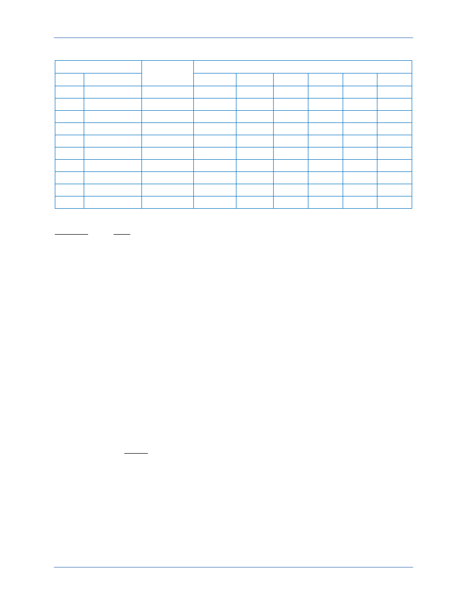
Table 4. Time Characteristic Curve Constants with SW3-3 Closed (On)
Curve Type
∗
Figure
Number †
Constants
BE1
Similar To
A
B
C
N
K
R
S
GE IAC 55
10
0.0286
0.0208
1.000
0.9844
0.028
0.0940
L
GE IAC 66
11
2.3955
0.00002
1.000
0.3125
0.028
7.8001
D
ABB CO-6
15
0.4797
0.21359
1.000
1.5625
0.028
0.8750
M
ABB CO-7
16
0.3022
0.12840
1.000
0.5000
0.028
1.7500
I
GE IAC 51
24
0.2747
0.1042
1.000
0.4375
0.028
0.8868
V
GE IAC 53
25
4.4309
0.0991
1.000
1.9531
0.028
5.8231
E
GE IAC 77
26
4.9883
0.0129
1.000
2.0469
0.028
4.7742
B
BS142-B ‡
20
1.4636
0.00000
1.000
1.0469
0.028
3.2500
C
BS142-C ‡
21
8.2506
0.00000
1.000
2.0469
0.028
8.0000
F
None §
N/A
0.0000
1.00000
0.000
0.0000
0.000
1.0000
∗ BE1 Curve Types:
S: Short Inverse
V: Very Inverse
L: Long Inverse
E: Extremely Inverse
D: Definite Time
B: BS142 Very Inverse
M: Moderately Inverse
C: BS142 Extremely Inverse
I: Inverse
F: Fixed Time Delay
† Figure numbers refer to the characteristic curves located in the
Time Characteristic Curves
chapter.
‡ Curves B and C are defined in British Standard BS142 and IEC Standard IEC 255-4.
§ Fixed time delay, adjustable from 0.1 to 9.9 seconds.
Integrating Reset
Reset begins when the current drops below 95% of pickup. Integrating reset simulates the disk reset of
electromechanical relays. BE1-50/51B-219 and BE1-50/51B-226 relays provide the integrating reset
function even when input current falls to zero.
Integrating reset characteristics are defined by the following equation and shown in Figure 9. Equation
constants are provided in Table 3 or Table 4.
Integrating Reset Equation:
1
M
RD
T
2
R
−
=
Where:
T
R
= Time to reset in seconds
R = Constant for the particular curve
D = TIME DIAL setting
M = Current in multiples of PICKUP setting during reset
BE1-50/51B-219/-226
Specifications