Audio Enhancement TLD100 User Manual
Page 8
8
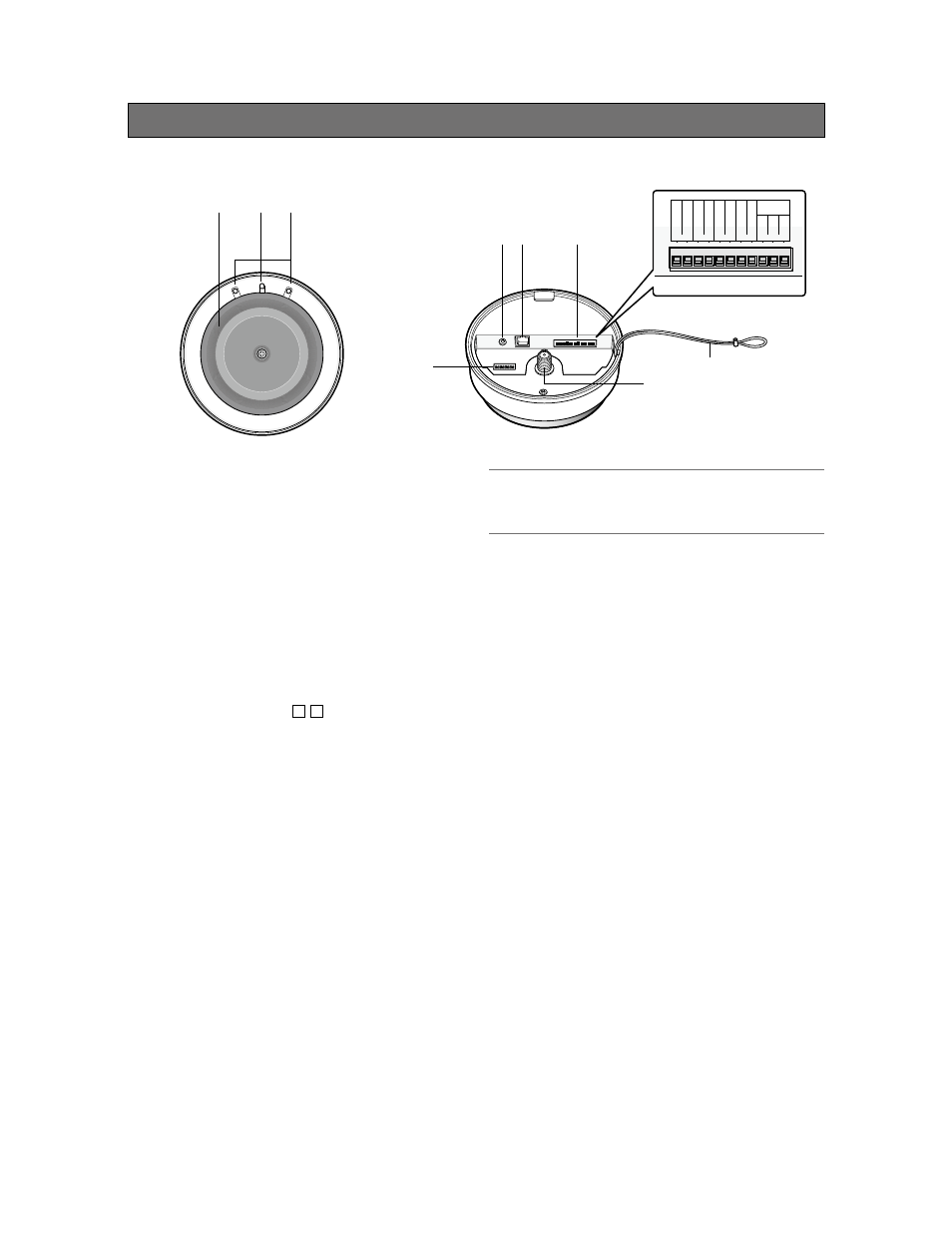
Major operating controls and their functions (IR-Satellite or Sensor)
Front
Back
① Infrared sensor cover
To receive only the infrared by the inner sensor, the
visible light is filtered out by this infrared sensor cover.
② Operation indicator [OPERATE]
(Green/Yellow/Red)
This LED lights green when the power is on and this
unit is receivable under normal conditions.
This LED lights as follows to indicate other states:
F2 signal output provided: red light
Page mute signal received: yellow light
See page 16 for further information on operation.
③ Reception indicator [ / ]
This LED lights green when this unit is receiving sig-
nals from each microphone under normal conditions.
This LED lights as follows to indicate other states:
F1 or F2 signal output provided: red light
Page mute signal received: yellow light
Feedback blocker in operation: yellow light
See page 16 for further information on operation.
④ LINE IN connector [LINE IN L/R]
This connector is used to provide an audio input from
external sources such as a projector or CD. This is a
stereo, line level input, and is internally mixed to a
monaural signal.
A stereo mini plug (ø3.5 mm) is used.
⑤ Conversion box connector
[TO CONVERSION BOX]
This connector is used to connect the cable to the
supplied conversion box.
A standard CAT5 or CAT5e cable is used to connect
to the conversion box.
CAUTION:
• DO NOT connect this device to any type of Ethernet
(LAN) system.
⑥ Control (Auxillary) terminals
An 11-pin Euro block is used.
The following terminals are equipped.
F1 CNT: provides F1 signal* output controlled by
MTD-09.
F2 CNT: provides F2 signal* output controlled by
MTD-09.
*
These are available when MTD-09 is used.
Settings of F1 and F2 are performed with
MTD-09.
F2 ACK: used to activate F2 ACK LED signal.
PAGE MUTE: provides signal inputs externally
when the paging function is used.
RS-232C: is used to control this unit via communica-
tion from an external device.
⑦ Safety strap
This strap is attached to the ceiling mount bracket and
prevents the sensor/receiver from dropping.
⑧ Extension sensor input connector
[EXT SENSOR]
This connector is used for sensor extension. A single
additional sensor (EDS-07) can be connected
directly to this connector. A total of 4 sensors can be
connected to this terminal with the additional coupler
(AE-DCF).
④ ⑤
⑥
⑨
③
②
①
⑧
⑦
SG
RS-232C
RxD
TxD
GND
GND
F2 ACK
F2 COM
F2 CNT
F1 COM
F1 CNT
PAGE MUTE
2
1